
Force on a current-carrying wire: the electric motor and the loudspeaker
Why does a loudspeaker cone vibrate and the blades of a desk fan turn, when nothing visible pushes either of them?
Prior knowledge
- A magnetic field exerts on a moving charged particle a force perpendicular to the velocity and the fieldchapter Charged particle in electric and magnetic fields
- The magnetic field of a straight current-carrying wire circles the wire, and its magnitude is $B = \mu_0 I : (2\pi r)$chapter Magnetic field of a wire and a coil
Core path: follow the steps in order. Tasks marked Optional give extra practice. Optional tasks: 4.
Think about it
When a loudspeaker plays a bass note, you can see its cone moving back and forth. The blades of a desk fan start to turn as soon as the plug is pushed into the wall. Nobody touches either of them, and neither has any burning fuel. Both, however, contain a magnet and a wire carrying an electric current.
How can a magnet make a wire move, if the wire is copper, which a magnet does not attract?
Optional Recall: the magnetic field of a straight wire
Predict
Make your predictions before investigating 2 questions
Prediction 1: does the balance feel the current?
Prediction 2: the wire oblique to the field
Investigate
In the current balance a magnet stands on the balance and a wire is between its poles. Change the current and the angle of the wire and follow the reading of the balance.
Simulation
How to use
Adjust the current $I$ and the angle $\alpha$ between the wire and the field, and choose the magnet and the length $l$ of wire in the field. A negative current means that the current flows in the opposite direction in the wire. The side view shows the balance, the magnet and the wire, and the force on the wire as a red arrow whose length shows the magnitude of the force. In the top view you see the poles of the magnet from above, the green field lines, the angle of the wire and the violet current arrow. The force points out of the page (a dot in a circle) or into the page (a cross in a circle). The reading of the balance is in the readings row and on the display of the balance.
Assumptions of the model
The field is uniform between the poles and zero outside them. Only the horizontal lower part of the wire is in the field; the forces on the vertical lead wires are horizontal and do not change the reading of the balance. The wire is rigidly fixed to the stand, so it does not move. The magnitudes of the fields of the magnets are not shown: they are determined from the measurements. The readings are values calculated by the model to a precision of $0.01\,\text{g}$, not measurements, and they contain no measurement error.
How the calculation works
The field exerts on the wire a vertical force $F = I l B \sin\alpha$. By Newton's third law the wire exerts on the magnet an equal and opposite force, so the balance shows the reading
$$m = m_0 + \frac{F}{g}$$
where $m_0 = 245.30\,\text{g}$ is the reading without a current and $g = 9.81\,\text{m/s}^2$. From the change in the reading $\Delta m = m - m_0$ we obtain the force $F = \Delta m \cdot g$ and from it the magnetic flux density $B = F : (I l)$, when the wire is perpendicular to the field.
Experiment 1: only the current changes
Test prediction 1. The wire is perpendicular to the field, and the magnet and the length of wire stay the same; change only the current. First record the reading without a current (the zero reading), then at least one positive and one negative current (a negative current flows in the opposite direction in the wire), for example $3.0\,\text{A}$, $6.0\,\text{A}$, $-3.0\,\text{A}$ and $-6.0\,\text{A}$. Calculate the change in the reading for each row.
Initial state: current = $0\,\text{A}$, angle = $90^\circ$, magnet: magnet A, wire in the field: $5.0\,\text{cm}$. Kept constant: angle, magnet, wire in the field. Varied: current.
| current | $m$ $(\text{g})$ |
|---|
Experiment 2: only the angle changes
Test prediction 2. The current is $6.0\,\text{A}$, and the magnet and the length of wire stay the same; change only the angle between the wire and the field. Record the reading at least at the angles $90^\circ$ and $30^\circ$, and if you wish also $60^\circ$ and $0^\circ$. The zero reading is the same as in experiment 1.
Initial state: current = $6\,\text{A}$, angle = $90^\circ$, magnet: magnet A, wire in the field: $5.0\,\text{cm}$. Kept constant: current, magnet, wire in the field. Varied: angle.
| angle | $m$ $(\text{g})$ |
|---|
Conclusion: the force and the field of the magnet
On the basis of your tables, write how the change in the reading depends on the current and its direction, and how it depends on the angle of the wire. From the numbers of experiment 1, calculate the force that the field exerts on the wire at $6.0\,\text{A}$, and determine the magnetic flux density of magnet A when $5.0\,\text{cm}$ of wire is in the field.
Model answer
Without a current the reading is $245.30\,\text{g}$. At $3.0\,\text{A}$ the change is $1.22\,\text{g}$ and at $6.0\,\text{A}$ $2.45\,\text{g}$, so the change is proportional to the current; with negative currents the reading falls by the same amount. At $6.0\,\text{A}$ the force is $F = \Delta m \cdot g = 0.00245\,\text{kg} \cdot 9.81\,\text{m/s}^2 = 0.0240\,\text{N}$, so $B = F : (I l) = 0.0240\,\text{N} : (6.0\,\text{A} \cdot 0.050\,\text{m}) = 0.080\,\text{T}$. In experiment 2 the change fell to half, $1.22\,\text{g}$, at $30^\circ$ and to zero at $0^\circ$, so the force is proportional to the sine of the angle: $F = I l B \sin\alpha$. The values are calculated by the model; in a real current balance the readings would vary slightly.
Assess your own answer
Tick the points your own answer already contains.
Review the theory summary and practise with the exercises.
Theory summary
Key idea
A magnetic field pushes a current-carrying wire
In the chapter Charged particle in electric and magnetic fields, a magnetic field exerted on a moving charged particle a force perpendicular to both the velocity of the particle and the field. An electric current in a wire is a motion of charges: the conduction electrons of the metal move along the wire. The magnetic field exerts a force on every moving electron, and the electrons pass it on to the metal of the wire, so the force acts on the whole wire. When a light copper wire is hung between the poles of a horseshoe magnet and a current is switched on, the wire swings sideways. Copper is not ferromagnetic, and the magnet does not attract it: the force appears only when there is a current in the wire.
The direction of the force
The force is always perpendicular to both the direction of the current and the magnetic field. Its direction is given by the right-hand rule: when the thumb of an outstretched right hand points in the direction of the current and the other fingers in the direction of the magnetic field, the force points out of the palm. It is the same rule as for a positively charged particle, because the direction of the current is the direction in which positive charge moves. When the direction of the current or of the field is reversed, the direction of the force reverses. If the wire is parallel to the field, there is no force at all.
The electric motor
In a direct-current motor, a current loop that can turn about an axle sits between the poles of a magnet. In the two sides of the loop that cross the field, the current flows in opposite directions, so the forces on them are in opposite directions. The forces are not on the same line, so they have a turning effect: they turn the loop. When the loop has turned to be perpendicular to the field, the forces point away from the axle and no longer turn it, and the loop keeps moving because of its inertia. Exactly then the commutator, a split ring with the carbon brushes that touch it, reverses the direction of the current in the loop. In this way the forces turn the loop in the same direction every half turn. A real motor has many coils and an iron core, so it turns smoothly and strongly.
The loudspeaker
The magnet of a loudspeaker is built so that in the ring-shaped gap the field points radially outwards. In the gap is a light voice coil, and every part of it is perpendicular to the field, so an equal force acts on every part in the direction of the axis of the coil. A radial field is essential: in a uniform field the forces on opposite sides of a closed coil would be in opposite directions and would cancel, so nothing would push the coil. The coil is attached to the cone. The alternating current from the amplifier changes its direction in step with the sound signal, so the force pushes the cone alternately forwards and backwards. The cone vibrates at the frequency of the signal, compresses and rarefies the air and produces a sound wave. The larger the current, the larger the force and the louder the sound. Most of the electrical energy delivered to the loudspeaker is, however, transformed into internal energy of the coil and the magnet.
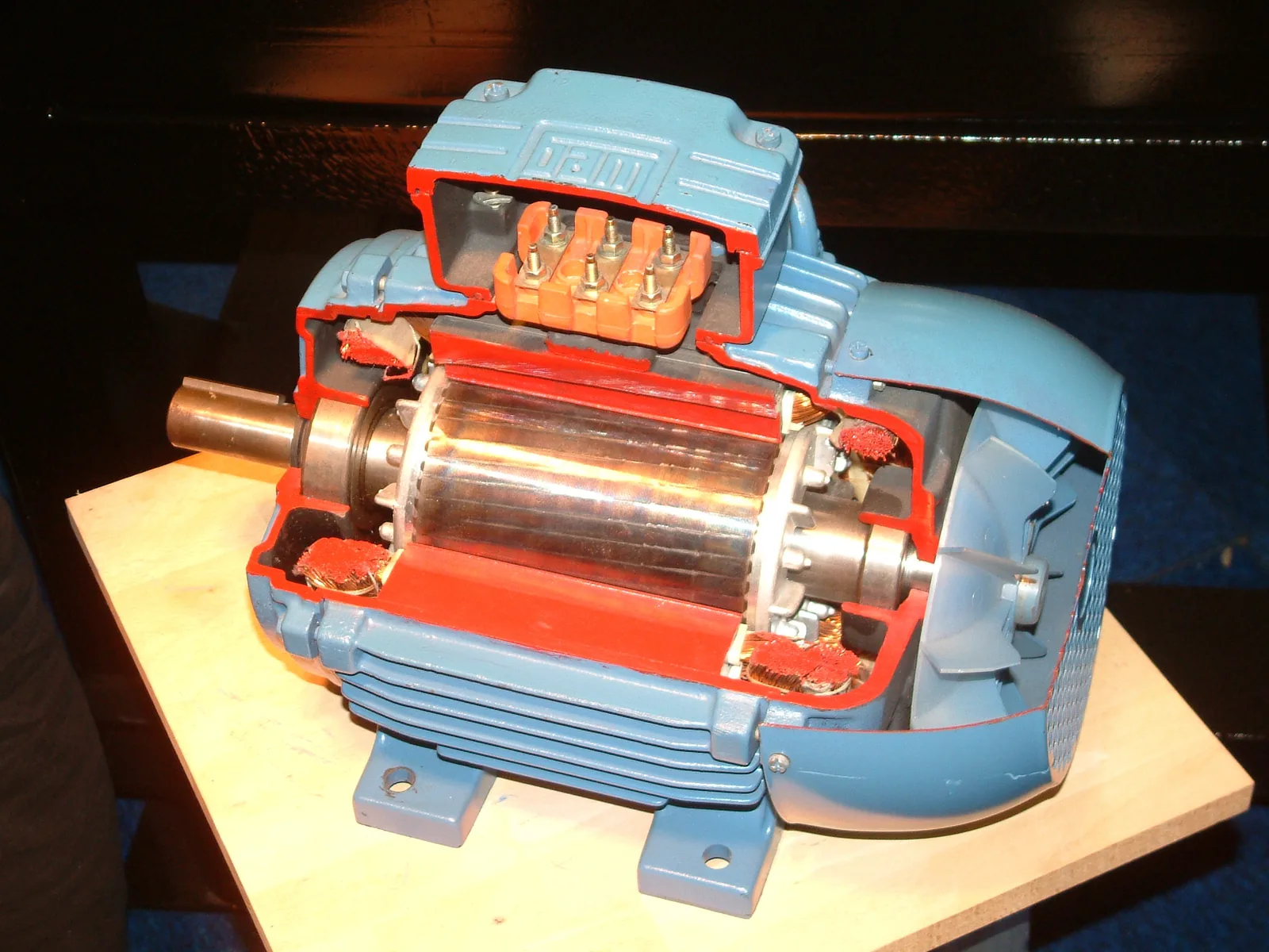
Force on a current-carrying wire
When a current $I$ flows in a straight wire and the wire is in a uniform magnetic field, the field exerts on the wire a force of magnitude
$$F = I l B \sin\alpha$$
where $F$ is the force (N), $I$ the current (A), $l$ the length of the part of the wire that is in the field (m), $B$ the magnetic flux density (T) and $\alpha$ the angle between the wire and the field. Only the component of the field perpendicular to the wire, $B \sin\alpha$, produces a force. The force is greatest when the wire is perpendicular to the field ($\sin 90^\circ = 1$) and zero when the wire is parallel to the field ($\sin 0^\circ = 0$). At an angle of $30^\circ$ the force is half of its greatest value, because $\sin 30^\circ = 0.5$. The formula gives the unit of the tesla: $1\,\text{T} = 1\,\tfrac{\text{N}}{\text{A}\cdot\text{m}}$.
The force between two current-carrying wires
There is a force between two parallel current-carrying wires, because each is in the magnetic field of the other. In the chapter Magnetic field of a wire and a coil, the field of wire $1$ circles around it, and at a distance $r$ its magnitude is $B_1$. At wire $2$ the field is perpendicular to wire $2$, so a force $F$ acts on the part of wire $2$ whose length is $l$:
$$\begin{aligned} &B_1 = \frac{\mu_0 I_1}{2\pi r} \\[6pt] &F = I_2 l B_1 \\ &\quad = \frac{\mu_0 I_1 I_2 l}{2\pi r} \end{aligned}$$
where $I_1$ and $I_2$ are the currents of the wires (A), $r$ is the distance between the wires (m), $l$ the length of the part that runs parallel (m) and $\mu_0 = 4\pi \cdot 10^{-7}\,\tfrac{\text{Vs}}{\text{Am}}$ the permeability of free space. By Newton's third law, an equal and opposite force acts on wire $1$. The right-hand rule shows that currents in the same direction attract each other and currents in opposite directions repel each other. Until 2019 the ampere was defined with this force: the current is $1\,\text{A}$ when the force between wires $1\,\text{m}$ apart is $2 \cdot 10^{-7}\,\text{N}$ for every metre of wire.
Common misconception
Many people think that a magnet attracts a wire and that the wire moves along the field lines towards the other pole. The force is, however, perpendicular to the field, and a copper or aluminium wire experiences a force only when it carries a current. When the direction of the current is reversed, the wire moves in the opposite direction, although the magnet is the same. Another common mistake is to conclude from the charges that currents in the same direction repel each other. The force between wires is magnetic, and currents in the same direction attract each other. A third mistake is to use the cosine in the formula: the angle $\alpha$ is the angle between the wire and the field, and the force is zero when the wire is parallel to the field.
Summary
- A magnetic field exerts on a current-carrying wire a force $F = I l B \sin\alpha$, where $\alpha$ is the angle between the wire and the field. The force is greatest when the wire is perpendicular to the field and zero when the wire is parallel to the field.
- The force is perpendicular to both the current and the field; its direction is given by the right-hand rule, and it reverses when the direction of the current or of the field reverses.
- Currents in the same direction attract each other, and currents in opposite directions repel each other. The force is $F = I_2 l B_1$, where $B_1 = \mu_0 I_1 : (2\pi r)$.
- In a direct-current motor the forces turn a current loop, and the commutator reverses the current every half turn.
- In a loudspeaker an alternating current in a radial field pushes the voice coil and the cone back and forth in step with the signal.
Optional Return to your predictions
Compare your predictions with the values of the model in the experiments and with the formula $F = I l B \sin\alpha$. Then return to the question at the start: how can a magnet move a copper wire that it does not attract? Also explain why the cone of a loudspeaker moves back and forth and not in only one direction.
Would you change your prediction?
Apply
Worked example
Problem
A loudspeaker voice coil has $60$ turns of thin wire, and the radius of the coil is $1.3\,\text{cm}$. The coil is in the gap of a magnet, where the magnetic flux density of the radial field is $0.95\,\text{T}$, and the field is perpendicular to the wire everywhere. How large is the force on the coil when the current is at its peak value of $1.5\,\text{A}$?
Step 1/7
Given and find. Number of turns $N = 60$, radius of the coil $r = 1.3\,\text{cm}$, magnetic flux density $B = 0.95\,\text{T}$, current $I = 1.5\,\text{A}$ and angle between the wire and the field $\alpha = 90^\circ$. We are asked for the force $F$ on the coil.
Step 2/7
Principle. The field is radial, so every part of the wire of the coil is perpendicular to the field, and the force on every part points in the same direction, along the axis of the coil. The forces therefore add up, and in the formula $F = I l B \sin\alpha$ the length $l$ is the whole length of the wire of the coil: $N$ turns, each with the length of the circumference of a circle, $2\pi r$.
Step 3/7
Formula solved.
$$\begin{aligned} l &= N \cdot 2\pi r \\ F &= I l B \sin 90^\circ = I l B \end{aligned}$$
Step 4/7
Unit conversions. The radius in metres:
The other quantities are in SI units.
Step 5/7
Substitution. First calculate the length of the wire and then the force:
$$\begin{aligned} l &= N \cdot 2\pi r \\ &= 60 \cdot 2\pi \cdot 0.013\,\text{m} \\ &= 4.9009\,\text{m} \\[6pt] F &= I l B \\ &= 1.5\,\text{A} \cdot 4.9009\,\text{m} \cdot 0.95\,\text{T} \\ &= 6.984\,\text{N} \end{aligned}$$
Step 6/7
Result. The force on the coil is $F \approx 7.0\,\text{N}$ along the axis of the coil. The result is given to two significant figures, like the radius $1.3\,\text{cm}$ and the current $1.5\,\text{A}$.
Step 7/7
Reasonableness. The units agree:
If the mass of the cone and the coil is about $10\,\text{g}$, their weight is only about $0.1\,\text{N}$, so the force is about $70$ times the weight. This is plausible, because the cone has to accelerate back and forth hundreds of times a second.
Optional Find the error
Apply to a new situation: jump leads
A car with a flat battery is started with the help of the battery of another car, using jump leads. When the starter motor turns the engine, a current of $150\,\text{A}$ flows in one lead and an equal current back in the other. The leads run parallel for $2.0\,\text{m}$, with the distance between their centres $1.5\,\text{cm}$.
How large is the force between the leads? Answer in newtons.
Hint 1: a guiding question
In what field is the second lead? What is the magnetic field of the first lead at the second lead, and in which direction does it point relative to the lead?
Hint 2: what is the connection
The field of the first lead at the second is $B_1 = \mu_0 I_1 : (2\pi r)$, and it is perpendicular to the second lead, so $F = I_2 l B_1$.
Hint 3: an intermediate step
and $F = 150\,\text{A} \cdot 2.0\,\text{m} \cdot B_1$.
Show the solution
Given
currents of the leads $I_1 = I_2 = 150\,\text{A}$ in opposite directions, length of the parallel part $l = 2.0\,\text{m}$, distance $r = 1.5\,\text{cm}$, $\mu_0 = 4\pi \cdot 10^{-7}\,\tfrac{\text{Vs}}{\text{Am}}$
Find
force $F$ between the leads in newtons
Principle
Each lead is in the magnetic field of the other. The field of the first lead circles around it, so at the second lead it is perpendicular to the lead and equally strong along the whole parallel stretch. A force $F = I_2 l B_1$ therefore acts on the second lead. The currents are in opposite directions, so the leads repel each other.
Formula
$B_1 = \dfrac{\mu_0 I_1}{2\pi r}$ and $F = I_2 l B_1$
Conversions
Substitution
Answer
$0.60\,\text{N}$
Two significant figures like the distance $1.5\,\text{cm}$ and the length $2.0\,\text{m}$. The leads repel each other.
Reasonableness
The field at the second lead is $B_1 = 2.0 \cdot 10^{-3}\,\text{T}$, about $40$ times the Earth's field but small compared with a magnet. The force corresponds to the weight of an object of about $60\,\text{g}$, so the leads may jerk slightly when the motor starts, but they do not jump.
Check your understanding
Exit ticket
Answer on your own first and only then open the answer.
- A current of $2.0\,\text{A}$ flows in a wire, and $0.30\,\text{m}$ of the wire is perpendicular to a magnetic field of $0.50\,\text{T}$. How large is the force on the wire?
Answer
$F$$= I l B$$= 2.0\,\text{A} \cdot 0.30\,\text{m} \cdot 0.50\,\text{T}$$= 0.30\,\text{N}$ - In a horizontal wire the current flows east, and the magnetic field points horizontally north. In which direction does the force on the wire point?
Answer
Upwards. When the thumb of the right hand points east (the current) and the other fingers north (the field), the palm points upwards. The force is perpendicular to both the current and the field.
1. Concept: the commutator
2. Calculate: an oblique wire
In a uniform magnetic field $B = 0.20\,\text{T}$ there is $0.50\,\text{m}$ of straight wire carrying a current of $4.0\,\text{A}$. The angle between the wire and the field is $30^\circ$.
How large is the force on the wire? Answer in newtons.
Hint 1: a guiding question
Which component of the field produces the force: the one along the wire or the one perpendicular to it?
Hint 2: what is the connection
$F = I l B \sin\alpha$, where $\alpha$ is the angle between the wire and the field.
Hint 3: an intermediate step
Show the solution
Given
$B = 0.20\,\text{T}$, $l = 0.50\,\text{m}$, $I = 4.0\,\text{A}$, angle between the wire and the field $\alpha = 30^\circ$
Find
force $F$ on the wire in newtons
Principle
The field is uniform and the wire straight, so the force is $F = I l B \sin\alpha$. The wire is oblique, so only the component of the field perpendicular to the wire, $B \sin\alpha$, produces a force.
Formula
$F = I l B \sin\alpha$
Conversions
None needed: the quantities are in SI units, and $\text{A} \cdot \text{m} \cdot \text{T} = \text{N}$.
Substitution
Answer
$0.20\,\text{N}$
Two significant figures like the data.
Reasonableness
For a perpendicular wire the force would be $0.40\,\text{N}$. For an oblique wire it must be smaller, and at $30^\circ$ it is exactly half, because $\sin 30^\circ = 0.5$.
Suggestion: one answer does not show everything you can do, but review the theory summary and do the core exercises.
Optional 3. Explain: the loudspeaker
Explain why the cone of a loudspeaker vibrates at the same frequency as the current from the amplifier. Also explain why the field of the loudspeaker magnet is made radial in the gap.
Model answer
The voice coil is in the gap of the magnet, and the field exerts on the wire of the coil a force $F = I l B$ along the axis of the coil. The direction of the force depends on the direction of the current. The alternating current from the amplifier changes direction in step with the signal, so the force pushes the coil, and the cone attached to it, alternately forwards and backwards at the same frequency. The cone compresses and rarefies the air, and a sound wave of the same frequency is produced. In a uniform field the forces on opposite sides of a closed coil would be in opposite directions and would cancel, so the coil would not move. In a radial field every part of the coil is perpendicular to the field, so the greatest possible force acts on every part and all the forces point in the same direction, along the axis. Then the coil moves straight back and forth and does not tilt.
Assess your own answer
Tick the points your own answer already contains.
Review the theory summary and practise with the exercises.
Review the chapter's concepts
Cards you mark Review later collect in your review deck.
- Force on a current-carrying wire
- The force on a wire carrying a current in a magnetic field.$$F = IlB\sin\alpha$$
Exercises
Level 1 · basic practice 5 exercises
One formula or one step of reasoning. Core exercises first, the rest is extra practice.
- Exercise 4-1Core
In a laboratory a straight wire is perpendicular to a uniform magnetic field. There is $0.40\,\text{m}$ of wire in the field, the current in the wire is $12\,\text{A}$ and the magnetic flux density is $0.050\,\text{T}$.
How large is the force on the wire?
Answer
$0.24\,\text{N}$
Show the solution
Given
length of the wire in the field $l = 0.40\,\text{m}$, current $I = 12\,\text{A}$, magnetic flux density $B = 0.050\,\text{T}$, wire perpendicular to the field, so $\alpha = 90^\circ$
Find
force $F$ on the wire in newtons
Principle
A magnetic field exerts a force on a current-carrying wire, because a magnetic force acts on the charges moving in the wire. The field is uniform and the wire is straight, so the formula $F = I l B \sin\alpha$ can be used for the whole piece of wire.
Formula
$F = I l B \sin\alpha$, and when $\alpha = 90^\circ$, $F = I l B$
Conversions
None needed: all quantities are in SI units, and $\text{A} \cdot \text{m} \cdot \text{T} = \text{N}$.
Substitution
$F$$= 12\,\text{A} \cdot 0.40\,\text{m} \cdot 0.050\,\text{T}$$= 0.24\,\text{N}$Answer
$0.24\,\text{N}$
Two significant figures like the data.
Reasonableness
The force is about the weight of a $25\,\text{g}$ object, which suits a laboratory magnet: the wire swings clearly, but the force is small. Doubling the current would double the force.
- Exercise 4-2Core
Between the poles of an electromagnet is a straight piece of wire $15\,\text{cm}$ long, at an angle of $40^\circ$ to the magnetic field. The current in the wire is $8.0\,\text{A}$ and the magnetic flux density is $0.25\,\text{T}$.
How large is the force on the piece of wire?
Answer
$0.19\,\text{N}$
Show the solution
Given
$l = 15\,\text{cm}$, $I = 8.0\,\text{A}$, $B = 0.25\,\text{T}$, angle between the wire and the field $\alpha = 40^\circ$
Find
force $F$ on the piece of wire in newtons
Principle
The wire is oblique to the field, so only the component of the field perpendicular to the wire, $B \sin\alpha$, produces a force. The field is uniform, so the force is $F = I l B \sin\alpha$.
Formula
$F = I l B \sin\alpha$
Conversions
$l$$= 15\,\text{cm}$$= 15 \cdot 0.01\,\text{m}$$= 0.15\,\text{m}$Substitution
$F$$= 8.0\,\text{A} \cdot 0.15\,\text{m} \cdot 0.25\,\text{T} \cdot \sin 40^\circ$$= 0.30\,\text{N} \cdot 0.6428$$= 0.1928\,\text{N}$Answer
$0.19\,\text{N}$
Two significant figures like the data.
Reasonableness
For a perpendicular wire the force would be $0.30\,\text{N}$. For an oblique wire it must be smaller, and $\sin 40^\circ \approx 0.64$ reduces it to about two thirds. With the cosine the result would wrongly be $0.23\,\text{N}$.
- Exercise 4-3
The horizontal piece of wire in a current balance is $6.0\,\text{cm}$ long and perpendicular to the field of the magnet. When a current of $4.5\,\text{A}$ flows in the wire, a force of $27\,\text{mN}$ acts on the piece of wire.
How large is the magnetic flux density between the poles of the magnet?
Answer
$0.10\,\text{T}$
Show the solution
Given
$l = 6.0\,\text{cm}$, $I = 4.5\,\text{A}$, $F = 27\,\text{mN}$, wire perpendicular to the field, so $\alpha = 90^\circ$
Find
magnetic flux density $B$ in teslas
Principle
The force that a field exerts on a straight current-carrying wire is $F = I l B \sin\alpha$. When the force, the current and the length are known, the magnitude of the field can be solved from the formula. A current balance is thus a way of measuring a magnetic field.
Formula
$F = I l B$, so $B = \dfrac{F}{I l}$
Conversions
$l$$= 6.0\,\text{cm}$$= 6.0 \cdot 0.01\,\text{m}$$= 0.060\,\text{m}$$F$$= 27\,\text{mN}$$= 27 \cdot 0.001\,\text{N}$$= 0.027\,\text{N}$Substitution
$B$$= \dfrac{0.027\,\text{N}}{4.5\,\text{A} \cdot 0.060\,\text{m}}$$= \dfrac{0.027\,\text{N}}{0.27\,\text{A}\cdot\text{m}}$$= 0.10\,\text{T}$Answer
$0.10\,\text{T}$
Two significant figures like the data.
Reasonableness
Between the poles of a horseshoe magnet the field is typically from hundredths to tenths of a tesla, so $0.10\,\text{T}$ is plausible. Check: $4.5\,\text{A} \cdot 0.060\,\text{m} \cdot 0.10\,\text{T} = 0.027\,\text{N}$.
- Exercise 4-4
A $100\,\text{m}$ section of power line between two pylons is horizontal and runs north–south as shown by a compass. A current of $200\,\text{A}$ flows in the wire.
The magnetic flux density of the Earth's magnetic field in southern Finland is about $53\,\mu\text{T}$, and the field points towards magnetic north and downwards at an angle of $74^\circ$ to the horizontal (WMM2025 model, NOAA/BGS). The angle between the wire and the field is therefore $74^\circ$.
How large is the force that the Earth's magnetic field exerts on the section of wire?
Answer
$1.0\,\text{N}$
Show the solution
Given
$l = 100\,\text{m}$, $I = 200\,\text{A}$, the Earth's field $B = 53\,\mu\text{T}$, angle between the wire and the field $\alpha = 74^\circ$
Find
force $F$ that the Earth's magnetic field exerts on the piece of wire, in newtons
Principle
Over a region the length of the wire the Earth's magnetic field is practically uniform, so the force is $F = I l B \sin\alpha$. The wire runs north–south as shown by a compass, and the field points towards magnetic north at $74^\circ$ to the horizontal, so the angle between the wire and the field is $74^\circ$.
Formula
$F = I l B \sin\alpha$
Conversions
$B$$= 53\,\mu\text{T}$$= 53 \cdot 10^{-6}\,\text{T}$Substitution
$F$$= 200\,\text{A} \cdot 100\,\text{m} \cdot 53 \cdot 10^{-6}\,\text{T} \cdot \sin 74^\circ$$= 1.06\,\text{N} \cdot 0.9613$$= 1.0189\,\text{N}$Answer
$1.0\,\text{N}$
Two significant figures like the magnetic flux density $53\,\mu\text{T}$.
Reasonableness
The force is about the weight of a $100\,\text{g}$ object over the whole $100\,\text{m}$, which is negligible compared with the weight of the wire: a power line carrying $200\,\text{A}$ weighs about $1\,\text{kg}$ per metre, so $100\,\text{m}$ of wire weighs about $1000\,\text{N}$. The Earth's field is weak, so the result is as expected.
- Exercise 4-5
Of the piece of wire in a current balance, $5.0\,\text{cm}$ is between the poles of a magnet, where the magnetic flux density is $0.20\,\text{T}$ and the field is perpendicular to the wire.
How large is the current in the wire when a force of $0.030\,\text{N}$ acts on the piece of wire?
Answer
$3.0\,\text{A}$
Show the solution
Given
$l = 5.0\,\text{cm}$, $B = 0.20\,\text{T}$, $F = 0.030\,\text{N}$, wire perpendicular to the field, so $\alpha = 90^\circ$
Find
current $I$ in the wire in amperes
Principle
The field exerts on a current-carrying wire a force $F = I l B \sin\alpha$, which is directly proportional to the current. When the force, the length and the field are known, the current can be solved.
Formula
$F = I l B$, so $I = \dfrac{F}{l B}$
Conversions
$l$$= 5.0\,\text{cm}$$= 5.0 \cdot 0.01\,\text{m}$$= 0.050\,\text{m}$Substitution
$I$$= \dfrac{0.030\,\text{N}}{0.050\,\text{m} \cdot 0.20\,\text{T}}$$= \dfrac{0.030\,\text{N}}{0.010\,\text{T}\cdot\text{m}}$$= 3.0\,\text{A}$Answer
$3.0\,\text{A}$
Two significant figures like the data.
Reasonableness
A current of a few amperes is usual for a laboratory power supply. Units:
$\tfrac{\text{N}}{\text{T}\cdot\text{m}}$$= \tfrac{\text{N}}{\frac{\text{N}}{\text{A}\cdot\text{m}}\cdot\text{m}}$$= \text{A}$
Level 2 · applied practice 4 exercises
Two steps, working with measured data, a unit conversion or rearranging a formula. Core exercises first, the rest is extra practice.
- Exercise 4-6Core
In a laboratory two parallel wires run side by side for $0.80\,\text{m}$ at a distance of $5.0\,\text{mm}$ from each other. A current of $10\,\text{A}$ flows in the same direction in both wires.
How large is the force on a wire in the magnetic field of the other wire? Give the answer in millinewtons.
Answer
$3.2\,\text{mN}$
Show the solution
Given
currents of the wires $I_1 = I_2 = 10\,\text{A}$ in the same direction, distance $r = 5.0\,\text{mm}$, length of the parallel part $l = 0.80\,\text{m}$, $\mu_0 = 4\pi \cdot 10^{-7}\,\tfrac{\text{Vs}}{\text{Am}}$
Find
force $F$ between the wires in millinewtons
Principle
The magnetic field of wire $1$ circles around it, so at wire $2$ it is perpendicular to wire $2$. The field at wire $2$ is the same along the whole length, because the distance stays the same. A force $F = I_2 l B_1$ therefore acts on wire $2$. Currents in the same direction attract each other.
Formula
$B_1 = \dfrac{\mu_0 I_1}{2\pi r}$ and $F = I_2 l B_1$
Conversions
$r$$= 5.0\,\text{mm}$$= 5.0 \cdot 0.001\,\text{m}$$= 0.0050\,\text{m}$Finally $1\,\text{mN} = 0.001\,\text{N}$.
Substitution
$B_1$$= \dfrac{4\pi \cdot 10^{-7}\,\tfrac{\text{Vs}}{\text{Am}} \cdot 10\,\text{A}}{2\pi \cdot 0.0050\,\text{m}}$$= 4.0 \cdot 10^{-4}\,\text{T}$$F$$= 10\,\text{A} \cdot 0.80\,\text{m} \cdot 4.0 \cdot 10^{-4}\,\text{T}$$= 0.0032\,\text{N}$$= 3.2\,\text{mN}$Answer
$3.2\,\text{mN}$
Two significant figures like the distance and the length. The wires attract each other.
Reasonableness
The field at wire $2$ is $B_1 = 4.0 \cdot 10^{-4}\,\text{T}$, less than a tenth of the field of a fridge magnet, so the force is small, about the weight of a $0.3\,\text{g}$ object. The force grows if the wires are brought closer together.
- Exercise 4-7Core
Students used a current balance to measure how much the reading of the balance changes when a current flows in the wire. There is $4.0\,\text{cm}$ of wire between the poles of the magnet, perpendicular to the field. The graph shows the change $\Delta m$ in the reading as a function of the current $I$, and a line fitted to the data points. Determine the magnetic flux density between the poles. Read the values you need from the line of the graph.
Answer
$0.074\,\text{T}$
Show the solution
Given
length of the wire in the field $l = 4.0\,\text{cm}$, wire perpendicular to the field; in the graph the change $\Delta m$ of the balance reading as a function of the current $I$; $g = 9.81\,\text{m/s}^2$
Find
magnetic flux density $B$ in teslas
Principle
The field exerts on the wire a force $F = I l B$, and by Newton's third law the wire exerts an equal and opposite force on the magnet. The reading of the balance therefore changes: the change $\Delta m$ corresponds to a force $F = \Delta m \cdot g$. The line passes through the origin, because without current there is no force.
Reading the graph
The data points deviate slightly from the line because of measurement uncertainty, so we use the line fitted to the points, which smooths out the deviations. The line passes through the origin and the grid point ($5.0\,\text{A}$; $1.50\,\text{g}$). We therefore read the current $I = 5.0\,\text{A}$ and the corresponding change $\Delta m = 1.50\,\text{g}$ from the line, not from a single data point: the last data point, $1.47\,\text{g}$, is slightly below the line.
Formula
$\Delta m \cdot g = I l B$, so $B = \dfrac{\Delta m \cdot g}{I l}$
Conversions
$\Delta m$$= 1.50\,\text{g}$$= 1.50 \cdot 0.001\,\text{kg}$$= 0.00150\,\text{kg}$$l$$= 4.0\,\text{cm}$$= 4.0 \cdot 0.01\,\text{m}$$= 0.040\,\text{m}$Substitution
$B$$= \dfrac{0.00150\,\text{kg} \cdot 9.81\,\text{m/s}^2}{5.0\,\text{A} \cdot 0.040\,\text{m}}$$= \dfrac{0.014715\,\text{N}}{0.20\,\text{A}\cdot\text{m}}$$= 0.0736\,\text{T}$Answer
$0.074\,\text{T}$
Two significant figures like the length $4.0\,\text{cm}$.
Reasonableness
The value is typical of a horseshoe magnet, of the order of a tenth of a tesla. Check with another point of the line: at $3.0\,\text{A}$ the line gives $0.90\,\text{g}$, and
$0.00090\,\text{kg} \cdot 9.81\,\text{m/s}^2 : (3.0\,\text{A} \cdot 0.040\,\text{m})$$= 0.074\,\text{T}$ - Exercise 4-8
In a uniform magnetic field with a magnetic flux density of $0.40\,\text{T}$ there is $0.50\,\text{m}$ of straight wire. When a current of $5.0\,\text{A}$ flows in the wire, a force of $0.50\,\text{N}$ acts on it.
How large is the angle between the wire and the field? Give the angle in the range $0^\circ$–$90^\circ$.
Answer
$30^\circ$
Show the solution
Given
$B = 0.40\,\text{T}$, $l = 0.50\,\text{m}$, $I = 5.0\,\text{A}$, $F = 0.50\,\text{N}$
Find
angle $\alpha$ between the wire and the field in degrees
Principle
The force depends on the angle between the wire and the field: $F = I l B \sin\alpha$. The greatest possible force, $I l B$, would be obtained with a perpendicular wire, so the ratio of the measured force to the greatest force gives the sine of the angle.
Formula
$F = I l B \sin\alpha$, so $\sin\alpha = \dfrac{F}{I l B}$ and $\alpha = \sin^{-1}\dfrac{F}{I l B}$
Conversions
None needed: the quantities are in SI units, and the expression for the sine has no unit.
Substitution
$\sin\alpha$$= \dfrac{0.50\,\text{N}}{5.0\,\text{A} \cdot 0.50\,\text{m} \cdot 0.40\,\text{T}}$$= \dfrac{0.50\,\text{N}}{1.0\,\text{N}}$$= 0.50$so $\alpha = \sin^{-1} 0.50 = 30^\circ$
Answer
$30^\circ$
To two significant figures like the data.
Reasonableness
For a perpendicular wire the force would be $1.0\,\text{N}$. The measured force is half of that, and half of the greatest force is obtained at the angle $30^\circ$, because $\sin 30^\circ = 0.5$.
- Exercise 4-9
Two horizontal metal rails are $8.0\,\text{cm}$ apart, and a metal rod of mass $20\,\text{g}$ lies across them. In the region of the rails there is a vertical magnetic field with a magnetic flux density of $0.30\,\text{T}$.
A current of $15\,\text{A}$ flows along one rail to the rod, through the rod and back along the other rail.
How large is the acceleration of the rod when friction is neglected?
Answer
$18\,\text{m/s}^2$
Show the solution
Given
distance between the rails, that is the part of the rod in the path of the current, $l = 8.0\,\text{cm}$, $B = 0.30\,\text{T}$ vertical, $I = 15\,\text{A}$, mass of the rod $m = 20\,\text{g}$, no friction
Find
acceleration $a$ of the rod in the unit $\text{m/s}^2$
Principle
The current flows through the rod from one rail to the other, so the $l = 8.0\,\text{cm}$ part of the rod is a current-carrying wire perpendicular to the vertical field. The force $F = I l B$ is horizontal and along the rails. The weight and the normal force of the rails cancel each other and there is no friction, so by Newton's second law $F = m a$.
Formula
$I l B = m a$, so $a = \dfrac{I l B}{m}$
Conversions
$l$$= 8.0\,\text{cm}$$= 8.0 \cdot 0.01\,\text{m}$$= 0.080\,\text{m}$$m$$= 20\,\text{g}$$= 20 \cdot 0.001\,\text{kg}$$= 0.020\,\text{kg}$Substitution
$a$$= \dfrac{15\,\text{A} \cdot 0.080\,\text{m} \cdot 0.30\,\text{T}}{0.020\,\text{kg}}$$= \dfrac{0.36\,\text{N}}{0.020\,\text{kg}}$$= 18\,\text{m/s}^2$Answer
$18\,\text{m/s}^2$
Two significant figures like the data.
Reasonableness
The acceleration is almost twice the acceleration of free fall, which is plausible for a light rod acted on by a force equal to the weight of a $36\,\text{g}$ object. In reality friction would reduce the acceleration.
Level 3 · challenging 3 exercises
Optional: application, two ideas together or a new situation where you reason for yourself.
- Exercise 4-10
A horizontal copper rod of mass $12\,\text{g}$ and length $20\,\text{cm}$ hangs from two light conducting wires. The rod is entirely in a uniform horizontal magnetic field with a magnetic flux density of $0.25\,\text{T}$, and perpendicular to the field.
A current is led to the rod through the wires.
How large must the current be for the wires to go slack, that is, for the magnetic force to support the whole weight of the rod?
Answer
$2.4\,\text{A}$
Show the solution
Given
mass of the rod $m = 12\,\text{g}$, length in the field $l = 20\,\text{cm}$, $B = 0.25\,\text{T}$, rod perpendicular to the horizontal field; $g = 9.81\,\text{m/s}^2$
Find
current $I$ at which the wires go slack
Principle
The wires are slack when their tension is zero. Then only the weight, downwards, and the magnetic force act on the rod. The rod is at rest, so by Newton's first law the forces must cancel: the magnetic force must point upwards and equal the weight. The field is horizontal and the rod is perpendicular to it, so the force $I l B$ is vertical; the direction of the current is chosen so that the force points upwards.
Formula
$I l B = m g$, so $I = \dfrac{m g}{l B}$
Conversions
$m$$= 12\,\text{g}$$= 12 \cdot 0.001\,\text{kg}$$= 0.012\,\text{kg}$$l$$= 20\,\text{cm}$$= 20 \cdot 0.01\,\text{m}$$= 0.20\,\text{m}$Substitution
$I$$= \dfrac{0.012\,\text{kg} \cdot 9.81\,\text{m/s}^2}{0.20\,\text{m} \cdot 0.25\,\text{T}}$$= \dfrac{0.11772\,\text{N}}{0.050\,\text{T}\cdot\text{m}}$$= 2.354\,\text{A}$Answer
$2.4\,\text{A}$
Two significant figures like the data.
Reasonableness
A current of a few amperes is enough to support a light rod, which suits a laboratory experiment. If the direction of the current were reversed, the force would point downwards and the wires would tighten: the tension would then be twice the weight.
- Exercise 4-11
Two parallel busbars at a substation are $0.30\,\text{m}$ apart. In a short circuit a current of $20\,\text{kA}$ flows momentarily in them in opposite directions.
How large is the force on a $1.0\,\text{m}$ length of a busbar, and do the busbars attract or repel each other?
Give the force as positive if the busbars attract each other and as negative if they repel each other.
Answer
$-270\,\text{N}$
Show the solution
Given
distance between the busbars $r = 0.30\,\text{m}$, currents $I_1 = I_2 = 20\,\text{kA}$ in opposite directions, length considered $l = 1.0\,\text{m}$, $\mu_0 = 4\pi \cdot 10^{-7}\,\tfrac{\text{Vs}}{\text{Am}}$
Find
force $F$ on a $1.0\,\text{m}$ length of a busbar and its direction; the force is given as positive if the busbars attract each other and negative if they repel each other
Principle
Each busbar is in the magnetic field of the other. The field of one busbar at the other is perpendicular to it and the same along its whole length, so the force is $F = I_2 l B_1$. Currents in opposite directions repel each other, so the force pushes the busbars apart.
Formula
$B_1 = \dfrac{\mu_0 I_1}{2\pi r}$ and $F = I_2 l B_1$
Conversions
$I_1$$= I_2$$= 20\,\text{kA}$$= 20 \cdot 1000\,\text{A}$$= 20\,000\,\text{A}$Substitution
$B_1$$= \dfrac{4\pi \cdot 10^{-7}\,\tfrac{\text{Vs}}{\text{Am}} \cdot 20\,000\,\text{A}}{2\pi \cdot 0.30\,\text{m}}$$= 0.013\,333\,\text{T}$$F$$= 20\,000\,\text{A} \cdot 1.0\,\text{m} \cdot 0.013\,333\,\text{T}$$= 266.7\,\text{N}$Answer
The magnitude of the force is $270\,\text{N}$, two significant figures like the current and the distance. The busbars repel each other, so by the sign rule of the task the answer is $-270\,\text{N}$.
Reasonableness
The field at the other busbar is $B_1 = 0.013\,\text{T}$ and the current is very large, so the force per metre corresponds to the weight of a $27\,\text{kg}$ object. This is why the busbars of a substation are fixed firmly: a short circuit could otherwise bend them.
- Exercise 4-12
A thin aluminium wire of length $1.0\,\text{m}$ and mass $2.7\,\text{g}$ is horizontal and runs east–west by the compass.
The magnetic flux density of the Earth's magnetic field in southern Finland is about $53\,\mu\text{T}$, and the field points towards magnetic north and downwards at an angle of $74^\circ$ to the horizontal (WMM2025 model, NOAA/BGS).
How large a current would have to flow in the wire for the Earth's magnetic field to support the weight of the wire? Give the answer in kiloamperes.
Answer
$1.8\,\text{kA}$
Show the solution
Given
length of the wire $l = 1.0\,\text{m}$, mass $m = 2.7\,\text{g}$, wire horizontal and east–west by the compass; the Earth's field $B = 53\,\mu\text{T}$ towards magnetic north and downwards at $74^\circ$ to the horizontal; $g = 9.81\,\text{m/s}^2$
Find
current $I$ in kiloamperes
Principle
Split the field into a horizontal and a vertical component. The wire runs east–west by the compass, so it is perpendicular to the horizontal component, which points to magnetic north, and also perpendicular to the vertical component. The vertical component exerts on the wire a horizontal force, which does not support the wire. The horizontal component $B_\text{horizontal} = B \cos 74^\circ$ points to magnetic north, and by the right-hand rule a current flowing east experiences from it a vertical force upwards. The wire stays in place when this force equals the weight.
Formula
$I l B \cos 74^\circ = m g$, so $I = \dfrac{m g}{l B \cos 74^\circ}$
Conversions
$m$$= 2.7\,\text{g}$$= 2.7 \cdot 0.001\,\text{kg}$$= 0.0027\,\text{kg}$$B$$= 53\,\mu\text{T}$$= 53 \cdot 10^{-6}\,\text{T}$Finally $1\,\text{kA} = 1000\,\text{A}$.
Substitution
$I$$= \dfrac{0.0027\,\text{kg} \cdot 9.81\,\text{m/s}^2}{1.0\,\text{m} \cdot 53 \cdot 10^{-6}\,\text{T} \cdot \cos 74^\circ}$$= \dfrac{0.026487\,\text{N}}{1.4609 \cdot 10^{-5}\,\text{T}\cdot\text{m}}$$= 1813\,\text{A}$$= 1.813\,\text{kA}$Answer
$1.8\,\text{kA}$
Two significant figures like the data.
Reasonableness
The required current is enormous: a thin wire would melt at once. The result shows how weak the Earth's magnetic field is, about $0.05\,\text{mT}$, compared with a tenth of a tesla for a laboratory magnet. A compass needle still turns, because it is a magnet and not a current-carrying wire.
