
The transformer and the transmission of electrical energy
Why is electricity carried from a power plant to a city at a voltage of $400\,\text{kV}$, when the voltage at a socket at home is only $230\,\text{V}$?
Prior knowledge
- A changing magnetic flux induces a voltage in a coilchapter Electromagnetic induction
- A generator produces an alternating voltage, and the effective value of the mains voltage is $230\,\text{V}$chapter The generator and alternating current
Core path: follow the steps in order. Tasks marked Optional give extra practice. Optional tasks: 4.
Think about it
The generator of a power plant produces a voltage of about $20\,\text{kV}$, and the voltage at the sockets in homes is $230\,\text{V}$. In between, the electricity travels hundreds of kilometres along the lines of the transmission grid, where the voltage is as high as $400\,\text{kV}$. So the voltage is first raised enormously and then lowered step by step. This requires expensive transformers and tall pylons.
Why is electricity not transmitted directly at the voltage of the generator, and how can a voltage be changed at all?
Optional Review: induction
Predict
Make your predictions before investigating 2 questions
Prediction 1: the transformer and a battery
Prediction 2: double the voltage
Investigate
A power plant sends power to a city along a power line. Choose the transmission voltage, the power and the length of the line, and watch how large a share of the power becomes internal energy in the line.
Simulation
How to use
Adjust the transmission voltage $U$, the transmitted power $P$ and the length of the line $l$. On the left of the picture is the power plant with its step-up transformer, in the middle the power line, and on the right the step-down transformer and the city. The line turns the redder, the larger the share of the power that becomes internal energy in it. The bars under the picture show the power that arrives (green) and the power loss (orange) on the same scale. From the Readings row you see the current of the line, its resistance and the turns ratio of the step-up transformer.
Assumptions of the model
The model treats the transmission in a simplified way as transmission along two conductors: the power $P$ is sent by the power plant at the voltage $U$, and the total resistance of the conductors is $R = 0.040\,\tfrac{\Omega}{\text{km}} \cdot l$. The real transmission grid is three-phase, but the dependence of the loss on the current is the same. The voltage of the generator is always $20\,\text{kV}$, and the transformers are assumed to be ideal. If the power loss would be greater than the power sent, the transmission is not possible, and the model says so. The readings are values calculated by the model, not measurements.
How the calculation works
The current of the line is obtained from the power and the transmission voltage, $I = P : U$, and the power that becomes internal energy in the line is
$$P_\text{h} = R I^2$$
The power that arrives is $P_\text{arriving} = P - P_\text{h}$, and the share of the loss is $P_\text{h} : P$. The turns ratio of the step-up transformer is $N_2 : N_1 = U : 20\,\text{kV}$.
Experiment 1: only the transmission voltage changes
Test prediction 2. The power is $200\,\text{MW}$ and the length of the line $150\,\text{km}$; change only the transmission voltage. Record at least the voltages $100\,\text{kV}$, $200\,\text{kV}$ and $400\,\text{kV}$, and if you wish also $50\,\text{kV}$. Compare how the current and the power loss change when the voltage doubles.
Initial state: transmission voltage = $100\,\text{kV}$, power = $200\,\text{MW}$, length of line = $150\,\text{km}$. Kept constant: power, length of line. Varied: transmission voltage.
| transmission voltage | $I$ $(\text{A})$ | $P_h$ $(\text{MW})$ | share $(\%)$ |
|---|
Conclusion: loss and voltage
On the basis of your table, write: how do the current and the power loss of the line change when the transmission voltage doubles? What is the dependence between the power loss and the voltage? What does this mean for a power plant that wants to transmit electricity far?
Model answer
When the voltage doubles from $100\,\text{kV}$ to $200\,\text{kV}$, the current halves from $2000\,\text{A}$ to $1000\,\text{A}$ and the power loss falls from $24\,\text{MW}$ to $6.0\,\text{MW}$, to a quarter. Likewise at $400\,\text{kV}$ the current is $500\,\text{A}$ and the loss $1.5\,\text{MW}$, only $0.75\,\%$ of the power. The current is inversely proportional to the voltage, $I = P : U$, and the loss is proportional to the square of the current, $P_\text{h} = R I^2$, so the loss is inversely proportional to the square of the voltage. That is why it pays to raise the voltage of the generator with a transformer to high voltage before the transmission and to lower it at the destination. The values are calculated by the model.
Assess your own answer
Tick the points your own answer already contains.
Review the theory summary and practise with the exercises.
Theory summary
Key idea
A transformer changes an alternating voltage
A transformer has a closed iron core and two coils wound around it. An alternating voltage is connected to the primary coil, and the voltage for the device is taken from the secondary coil. The coils do not touch each other, and no current flows between them along a conductor. The alternating current of the primary coil produces in the iron core a magnetic field whose magnitude and direction vary in step with the current. The iron core guides almost the whole magnetic flux around the core and so also through the secondary coil. In the chapter Electromagnetic induction we saw that a changing magnetic flux induces a voltage in a coil. Therefore an alternating voltage is produced in the secondary coil, with the same frequency as the primary voltage.
The number of turns decides the voltage
The same changing magnetic flux passes through every turn of both coils, so an equal voltage is induced in every turn. The voltage of a coil is the sum of the voltages of its turns, so it is proportional to the number of turns. In an ideal transformer the ratio of the primary and secondary voltages is therefore the same as the ratio of the numbers of turns of the coils, the turns ratio. When the secondary coil has more turns than the primary coil, the transformer raises the voltage (a step-up transformer). When the secondary coil has fewer turns, the transformer lowers the voltage (a step-down transformer).
A transformer works only with alternating current
If the primary coil is connected to a battery, a direct current flows in the coil, and the magnetic field of the iron core is constant. A constant magnetic flux does not induce a voltage, so the voltage of the secondary coil is zero. A voltage pulse is produced only at the moment when the current is switched on or off, because then the flux changes. This is why the power grid uses alternating current: in the chapter The generator and alternating current a generator produces an alternating voltage, and with transformers its size can be changed to suit each purpose.
Power is conserved, current changes
An ideal transformer does not consume energy, so the power coming into the primary coil is equal to the power leaving the secondary coil. Power is the product of voltage and current, so when a transformer raises the voltage tenfold, the current falls to a tenth. A transformer therefore does not add energy or power: it exchanges a large current for a high voltage or the other way round. In a real transformer some of the energy becomes internal energy in the resistance of the coils and in the eddy currents of the iron core. That is why the core is built of thin plates insulated from each other (chapter Lenz's law and eddy currents). The efficiency of large power-plant transformers is over $99\,\%$.
Transmission loss and high voltage
A power line has resistance, and the current flowing in the line heats it. The power that becomes internal energy is proportional to the square of the current, so it pays to keep the current small. The same power can be transmitted at a high voltage and a small current. When the voltage is raised tenfold, the current falls to a tenth and the power loss to a hundredth. That is why the voltage of the generator of a power plant is raised with a transformer to high voltage. The voltages of the Finnish transmission grid, maintained by Fingrid, are $400\,\text{kV}$, $220\,\text{kV}$ and $110\,\text{kV}$. The losses of the transmission grid correspond to about $2\,\%$ of the electricity used in Finland (Fingrid, Yhteisillä linjoilla 2026, data for 2025).
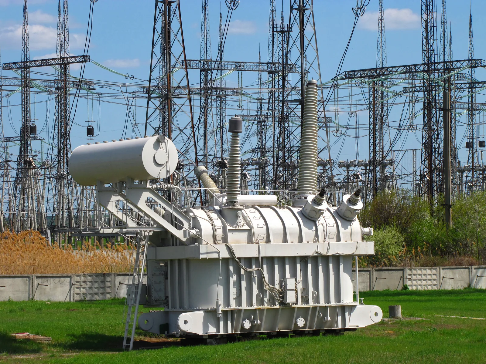
The voltage is lowered step by step
At substations, transformers lower the voltage to $110\,\text{kV}$ in the regional network and $20\,\text{kV}$ in the distribution network, and the local substation of a residential area lowers it to the $230\,\text{V}$ of homes. High voltage is not brought into homes, because insulating it requires long insulators and large distances, and touching it would be fatal (chapter Electrical safety). The charger of a phone lowers the voltage still further to about $5\,\text{V}$. A modern charger first changes the mains voltage to a very high frequency, so that the transformer can be small, and rectifies it at the end. The coils of the charger's transformer do not touch each other, so the phone is not conductively connected to the power grid.
Transformer and transmission loss
The voltages and currents of an ideal transformer depend on the numbers of turns of the coils:
$$\frac{U_1}{U_2} = \frac{N_1}{N_2} = \frac{I_2}{I_1}$$
where $U_1$ is the primary voltage (V), $U_2$ the secondary voltage (V), $N_1$ and $N_2$ the numbers of turns of the primary and secondary coils and $I_1$ and $I_2$ the primary and secondary currents (A). The ratio $N_1 : N_2$ is the turns ratio. The latter equality follows from the conservation of power: $U_1 I_1 = U_2 I_2$. The voltages and currents are effective (rms) values (chapter The generator and alternating current). When the voltage increases, the current decreases in the same proportion.
Power loss of a transmission line
A power plant sends a power $P$ at a voltage $U$. The current of the line and the power that becomes internal energy in the line are
$$\begin{aligned} P &= U I \\[6pt] P_\text{h} &= R I^2 = \frac{R P^2}{U^2} \end{aligned}$$
where $P$ is the transmitted power (W), $U$ the transmission voltage (V), $I$ the current of the line (A), $R$ the total resistance of the conductors (Ω) and $P_\text{h}$ the power loss (W). When the same power is transmitted at double the voltage, the current halves and the power loss falls to a quarter. The transmission voltage $U$ is not the voltage across the resistance of the line: the voltage drop between the ends of the line is only $R I$, so the power loss must not be calculated with the expression $U^2 : R$.
Common misconception
Many people calculate the power loss of a power line with the expression $P = U^2 : R$ and conclude that a higher voltage increases the losses. In that expression, however, $U$ is the voltage across the resistor. The transmission voltage is the voltage between the conductors, or between the conductors and the ground, and across the resistance of the line there is only a small voltage drop $R I$. The correct way is to calculate first the current $I = P : U$ and then the power loss $P_\text{h} = R I^2$: a higher voltage reduces the current and the losses. Another mistake is to think that a transformer that raises the voltage increases the power. In an ideal transformer power is conserved, so when the voltage increases, the current decreases. A third mistake is to assume that a transformer also works with a battery. It needs a changing magnetic flux, that is, alternating current.
Summary
- In a transformer the alternating current of the primary coil produces a changing magnetic flux in the iron core, and the flux induces an alternating voltage in the secondary coil. With direct current the flux does not change, and the transformer does not work.
- In an ideal transformer $U_1 : U_2 = N_1 : N_2 = I_2 : I_1$. Power is conserved, so when the voltage increases, the current decreases.
- The power loss of a transmission line is $P_\text{h} = R I^2$, where $I = P : U$. Double the transmission voltage reduces the loss to a quarter.
- Electricity is transmitted over long distances at high voltage: the voltages of the Finnish transmission grid are $400\,\text{kV}$, $220\,\text{kV}$ and $110\,\text{kV}$, and transformers lower the voltage step by step to the $230\,\text{V}$ of homes.
Optional Return to your predictions
Compare your predictions with the theory and with the values of the model in the experiment. Then return to the opening question: why is electricity not transmitted at the generator voltage of $20\,\text{kV}$, and why does changing the voltage require alternating current?
Would you change your prediction?
Apply
Worked example
Problem
The transformer of a substation lowers the voltage of the regional network, $110\,\text{kV}$, to the distribution network voltage of $20\,\text{kV}$. The secondary coil has $360$ turns, and the current going into the distribution network is $450\,\text{A}$. How many turns does the primary coil have, and how large a current flows in the primary coil? Assume the transformer to be ideal.
Step 1/7
Given and find. Primary voltage $U_1 = 110\,\text{kV}$, secondary voltage $U_2 = 20\,\text{kV}$, number of turns of the secondary coil $N_2 = 360$ and secondary current $I_2 = 450\,\text{A}$. We are asked for the number of turns $N_1$ of the primary coil and the primary current $I_1$.
Step 2/7
Principle. In an ideal transformer the same changing magnetic flux passes through both coils, so the voltages are in the same ratio as the numbers of turns. The transformer does not consume energy, so power is conserved, $U_1 I_1 = U_2 I_2$, and the currents are in inverse proportion to the voltages.
Step 3/7
Formula solved.
$$\begin{aligned} \frac{U_1}{U_2} &= \frac{N_1}{N_2} \;\Rightarrow\; N_1 = \frac{N_2 U_1}{U_2} \\[6pt] \frac{U_1}{U_2} &= \frac{I_2}{I_1} \;\Rightarrow\; I_1 = \frac{I_2 U_2}{U_1} \end{aligned}$$
Step 4/7
Unit conversions. Not needed: in both formulas the voltages form a quotient, so the kilovolts cancel. Both voltages are in the same unit, $\text{kV}$.
Step 5/7
Substitution. $$\begin{aligned} &N_1 = \frac{N_2 U_1}{U_2} \\ &= \frac{360 \cdot 110\,\text{kV}}{20\,\text{kV}} \\ &= 1980 \\[6pt] &I_1 = \frac{I_2 U_2}{U_1} \\ &= \frac{450\,\text{A} \cdot 20\,\text{kV}}{110\,\text{kV}} \\ &= 81.82\,\text{A} \end{aligned}$$
Step 6/7
Result. The primary coil has $1980$ turns, and the primary current is $I_1 \approx 82\,\text{A}$. The current is given to two significant figures, like the voltage $20\,\text{kV}$.
Step 7/7
Reasonableness. The transformer lowers the voltage, so the primary coil must have more turns and a smaller current than the secondary coil, as in the result. Power is conserved: $110\,\text{kV} \cdot 81.82\,\text{A} = 9.0\,\text{MW}$ and $20\,\text{kV} \cdot 450\,\text{A} = 9.0\,\text{MW}$.
Optional Find the error
Apply to a new situation: the connection line of a wind farm
A wind farm feeds a power of $33\,\text{MW}$ to a substation along a $110\,\text{kV}$ power line. The total resistance of the conductors is $8.0\,\Omega$.
How large a power becomes internal energy in the line? Answer in kilowatts.
Hint 1: a guiding question
The line is heated by the current. How is the current obtained when the power and the transmission voltage are known?
Hint 2: what is the connection
The current is $I = P : U$, and the power loss $P_\text{h} = R I^2$.
Hint 3: an intermediate step
so $P_\text{h} = 8.0\,\Omega \cdot (300\,\text{A})^2$.
Show the solution
Given
power $P = 33\,\text{MW}$, transmission voltage $U = 110\,\text{kV}$, total resistance of the conductors $R = 8.0\,\Omega$
Find
the power $P_\text{h}$ that becomes internal energy in the line, in kilowatts
Principle
In the resistance of the line the current changes electrical energy into internal energy at the rate $P_\text{h} = R I^2$. The current is obtained from the transmitted power and the transmission voltage, because $P = U I$. The transmission voltage is not across the resistance of the line, so the expression $U^2 : R$ cannot be used.
Formula
$P = U I$, so $I = \dfrac{P}{U}$, and $P_\text{h} = R I^2$
Conversions
Finally $1\,\text{kW} = 1000\,\text{W}$.
Substitution
Answer
$720\,\text{kW}$
Or $7.2 \cdot 10^{2}\,\text{kW}$, two significant figures like the power $33\,\text{MW}$ and the resistance $8.0\,\Omega$.
Reasonableness
The loss is $720\,\text{kW} : 33\,000\,\text{kW} \approx 2.2\,\%$ of the transmitted power, the same order of magnitude as the share of loss in the transmission grid reported by Fingrid, about $2\,\%$. The loss is a small part of the power, as it should be in a working grid.
Check your understanding
Exit ticket
Answer on your own first and only then open the answer.
- The primary coil of a transformer has $500$ turns and the secondary coil $25$ turns. The primary voltage is $230\,\text{V}$. How large is the secondary voltage?
Answer
$U_2$$= U_1 N_2 : N_1$$= 230\,\text{V} \cdot 25 : 500$$= 11.5\,\text{V}$The secondary coil has fewer turns, so the transformer lowers the voltage.
- The current of a transmission line falls to a third, and the resistance of the line stays the same. How does the power that becomes internal energy in the line change?
Answer
It falls to a ninth, because $P_\text{h} = R I^2$ and $(1 : 3)^2 = 1 : 9$.
1. Concept: why high voltage
2. Calculate: a lamp transformer
The ideal transformer of a low-voltage luminaire lowers the mains voltage $230\,\text{V}$ to a voltage of $12\,\text{V}$. The total power of the lamps connected to the secondary coil is $60\,\text{W}$.
How large a current flows in the primary coil? Answer in amperes.
Hint 1: a guiding question
An ideal transformer does not consume energy. So what is the power coming into the primary coil?
Hint 2: what is the connection
The primary power is $60\,\text{W}$, and $P = U_1 I_1$.
Hint 3: an intermediate step
$I_1 = 60\,\text{W} : 230\,\text{V}$.
Show the solution
Given
primary voltage $U_1 = 230\,\text{V}$, secondary voltage $U_2 = 12\,\text{V}$, power of the lamps $P = 60\,\text{W}$, ideal transformer
Find
the primary current $I_1$ in amperes
Principle
An ideal transformer does not consume energy, so the power coming into the primary coil is the same as the power leaving the secondary coil for the lamps, $U_1 I_1 = U_2 I_2 = P$.
Formula
$P = U_1 I_1$, so $I_1 = \dfrac{P}{U_1}$
Conversions
None needed: the power is in watts and the voltage in volts, and $\tfrac{\text{W}}{\text{V}} = \text{A}$.
Substitution
Answer
$0.26\,\text{A}$
Two significant figures like the power $60\,\text{W}$.
Reasonableness
The secondary current is $60\,\text{W} : 12\,\text{V} = 5.0\,\text{A}$. The primary current of a step-down transformer must be smaller, and the ratio $5.0\,\text{A} : 0.26\,\text{A} \approx 19$ is the same as the ratio of the voltages $230\,\text{V} : 12\,\text{V} \approx 19$.
Suggestion: one answer does not show everything you can do, but review the theory summary and do the core exercises.
Optional 3. Explain: the transformer in the power grid
Explain how a transformer changes a voltage. Also explain why the power grid uses alternating current and not direct current, when the voltage has to be changed on the way from the power plant to the home.
Model answer
The alternating current in the primary coil produces in the iron core a magnetic flux that changes in time with the current. The iron core guides the flux through the secondary coil as well, and the changing flux induces an equal voltage in every turn of the secondary coil. Therefore the voltage of a coil is proportional to its number of turns, and in an ideal transformer $U_1 : U_2 = N_1 : N_2$. Power is conserved, so when the voltage increases, the current decreases. Direct current produces a constant flux, which does not induce a voltage, so a transformer does not work with direct current. An alternating voltage can be raised with transformers to high voltage for the transmission, when the current and the losses $P_\text{h} = R I^2$ are small, and lowered at the destination to a safe $230\,\text{V}$.
Assess your own answer
Tick the points your own answer already contains.
Review the theory summary and practise with the exercises.
Review the chapter's concepts
Cards you mark Review later collect in your review deck.
- Transformer
- A device that changes the size of an alternating voltage in the ratio of the numbers of turns in its coils.
Exercises
Level 1 · basic practice 5 exercises
One formula or one step of reasoning. Core exercises first, the rest is extra practice.
- Exercise 8-1Core
The primary coil of a doorbell transformer has $1200$ turns and the secondary coil $60$ turns. The primary coil is connected to the mains voltage $230\,\text{V}$.
How large is the secondary voltage? Assume the transformer to be ideal.
Answer
$11.5\,\text{V}$
Show the solution
Given
number of turns of the primary coil $N_1 = 1200$, of the secondary coil $N_2 = 60$, primary voltage $U_1 = 230\,\text{V}$, ideal transformer
Find
the secondary voltage $U_2$ in volts
Principle
In the iron core of a transformer the same changing magnetic flux passes through every turn of both coils, so an equal voltage is induced in every turn. Therefore the voltages of an ideal transformer are in the same ratio as the numbers of turns.
Formula
$\dfrac{U_1}{U_2} = \dfrac{N_1}{N_2}$, so $U_2 = \dfrac{U_1 N_2}{N_1}$
Conversions
Not needed: the ratio of the numbers of turns has no unit, and the voltage comes out in volts.
Substitution
$U_2$$= \dfrac{230\,\text{V} \cdot 60}{1200}$$= 11.5\,\text{V}$Answer
$11.5\,\text{V}$
Three significant figures like the voltage $230\,\text{V}$; the numbers of turns are exact numbers.
Reasonableness
The secondary coil has $20$ times fewer turns, so the voltage must be $20$ times smaller: $230\,\text{V} : 20 = 11.5\,\text{V}$. A small voltage like this suits a doorbell and is safe to touch.
- Exercise 8-2Core
The ideal transformer of a garden light lowers the mains voltage $230\,\text{V}$ to a voltage of $8.0\,\text{V}$. The secondary coil has $40$ turns.
How many turns does the primary coil have?
Answer
$1150$
Show the solution
Given
primary voltage $U_1 = 230\,\text{V}$, secondary voltage $U_2 = 8.0\,\text{V}$, number of turns of the secondary coil $N_2 = 40$, ideal transformer
Find
the number of turns $N_1$ of the primary coil
Principle
In an ideal transformer the same changing magnetic flux passes through both coils, so the same voltage is induced in every turn and the voltages of the coils are in the same ratio as the numbers of turns.
Formula
$\dfrac{U_1}{U_2} = \dfrac{N_1}{N_2}$, so $N_1 = \dfrac{N_2 U_1}{U_2}$
Conversions
Not needed: in the ratio of the voltages the volts cancel.
Substitution
$N_1$$= \dfrac{40 \cdot 230\,\text{V}}{8.0\,\text{V}}$$= 1150$Answer
$1150$
Turns. The number of turns is a whole number, and the two significant figures of the voltage $8.0\,\text{V}$ are enough for this precision.
Reasonableness
The voltage falls by a factor of about $29$ ($230\,\text{V} : 8.0\,\text{V} \approx 29$), so the primary coil must have about $29$ times as many turns as the secondary coil: $29 \cdot 40 \approx 1150$.
- Exercise 8-3
The local substation of a residential area lowers the voltage of the distribution network, $20\,\text{kV}$, to $400\,\text{V}$. The current going into the low-voltage network is $250\,\text{A}$.
How large a current flows in the primary coil of the transformer, when the transformer is assumed to be ideal?
Answer
$5.0\,\text{A}$
Show the solution
Given
primary voltage $U_1 = 20\,\text{kV}$, secondary voltage $U_2 = 400\,\text{V}$, secondary current $I_2 = 250\,\text{A}$, ideal transformer
Find
the primary current $I_1$ in amperes
Principle
An ideal transformer does not consume energy, so power is conserved, $U_1 I_1 = U_2 I_2$. Therefore the currents are in inverse proportion to the voltages.
Formula
$\dfrac{U_1}{U_2} = \dfrac{I_2}{I_1}$, so $I_1 = \dfrac{I_2 U_2}{U_1}$
Conversions
$U_1$$= 20\,\text{kV}$$= 20 \cdot 1000\,\text{V}$$= 20\,000\,\text{V}$so that the voltages are in the same unit.
Substitution
$I_1$$= \dfrac{250\,\text{A} \cdot 400\,\text{V}}{20\,000\,\text{V}}$$= 5.0\,\text{A}$Answer
$5.0\,\text{A}$
Two significant figures like the voltage $20\,\text{kV}$.
Reasonableness
Power is conserved: $20\,000\,\text{V} \cdot 5.0\,\text{A} = 100\,\text{kW}$ and $400\,\text{V} \cdot 250\,\text{A} = 100\,\text{kW}$. The primary current of a step-down transformer is smaller than the secondary current, as it should be.
- Exercise 8-4
The total resistance of the conductors of a distribution line is $2.5\,\Omega$, and a current of $120\,\text{A}$ flows in the line.
How large a power becomes internal energy in the line? Give the answer in kilowatts.
Answer
$36\,\text{kW}$
Show the solution
Given
total resistance of the conductors $R = 2.5\,\Omega$, current $I = 120\,\text{A}$
Find
the power $P_\text{h}$ that becomes internal energy in the line, in kilowatts
Principle
In the resistance of the line the current changes electrical energy into internal energy. When the current and the resistance of the line are known, the power loss is obtained directly from the expression $P_\text{h} = R I^2$.
Formula
$P_\text{h} = R I^2$
Conversions
Finally $1\,\text{kW} = 1000\,\text{W}$.
Substitution
$P_\text{h}$$= 2.5\,\Omega \cdot (120\,\text{A})^2$$= 2.5\,\Omega \cdot 14\,400\,\text{A}^2$$= 36\,000\,\text{W}$$= 36\,\text{kW}$Answer
$36\,\text{kW}$
Two significant figures like the resistance $2.5\,\Omega$.
Reasonableness
Units:
$\Omega \cdot \text{A}^2$$= \tfrac{\text{V}}{\text{A}} \cdot \text{A}^2$$= \text{V} \cdot \text{A}$$= \text{W}$The loss corresponds to the power of about five electric stoves; in a distribution line such a power can be lost when the current is over a hundred amperes.
- Exercise 8-5
A current of $800\,\text{A}$ flows in a $400\,\text{kV}$ line of the transmission grid. How large a power does the line transmit? Give the answer in megawatts.
Answer
$320\,\text{MW}$
Show the solution
Given
transmission voltage $U = 400\,\text{kV}$, current $I = 800\,\text{A}$
Find
the transmitted power $P$ in megawatts
Principle
Electric power is the product of voltage and current. The power transmitted by a line is the product of the transmission voltage and the current of the line.
Formula
$P = U I$
Conversions
$U$$= 400\,\text{kV}$$= 400 \cdot 1000\,\text{V}$$= 400\,000\,\text{V}$Finally $1\,\text{MW} = 1\,000\,000\,\text{W}$.
Substitution
$P$$= 400\,000\,\text{V} \cdot 800\,\text{A}$$= 320\,000\,000\,\text{W}$$= 320\,\text{MW}$Answer
$320\,\text{MW}$
Three significant figures like the given values.
Reasonableness
$320\,\text{MW}$ is of the order of magnitude of the power of a large power plant, and a line of the transmission grid transmits just such powers. The same power at $230\,\text{V}$ would require a current of over a million amperes.
Level 2 · applied practice 4 exercises
Two steps, working with measured data, a unit conversion or rearranging a formula. Core exercises first, the rest is extra practice.
- Exercise 8-6Core
A hydroelectric power plant transmits a power of $50\,\text{MW}$ at a voltage of $110\,\text{kV}$ to a substation. The total resistance of the conductors is $4.0\,\Omega$.
How large a power becomes internal energy in the line? Give the answer in kilowatts.
Answer
$8.3 \cdot 10^{2}\,\text{kW}$
Show the solution
Given
power $P = 50\,\text{MW}$, transmission voltage $U = 110\,\text{kV}$, resistance of the conductors $R = 4.0\,\Omega$
Find
the power $P_\text{h}$ that becomes internal energy in the line, in kilowatts
Principle
The line is heated by its current, and the power loss is $P_\text{h} = R I^2$. The current is obtained from the power and the transmission voltage, because $P = U I$. The transmission voltage is not across the resistance of the line, so the loss is not calculated with the expression $U^2 : R$.
Formula
$P = U I$, so $I = \dfrac{P}{U}$, and $P_\text{h} = R I^2$
Conversions
$P$$= 50\,\text{MW}$$= 50 \cdot 10^{6}\,\text{W}$$U$$= 110\,\text{kV}$$= 110 \cdot 10^{3}\,\text{V}$Finally $1\,\text{kW} = 1000\,\text{W}$.
Substitution
$I$$= \dfrac{50 \cdot 10^{6}\,\text{W}}{110 \cdot 10^{3}\,\text{V}}$$= 454.5\,\text{A}$$P_\text{h}$$= 4.0\,\Omega \cdot (454.5\,\text{A})^2$$= 826\,400\,\text{W}$$= 826.4\,\text{kW}$Answer
$8.3 \cdot 10^{2}\,\text{kW}$
Or about $830\,\text{kW}$, two significant figures like the power $50\,\text{MW}$ and the resistance $4.0\,\Omega$.
Reasonableness
The loss is $0.83\,\text{MW} : 50\,\text{MW} \approx 1.7\,\%$ of the transmitted power, of the same order of magnitude as the losses of the transmission grid, about $2\,\%$. So the loss is small but not negligible.
- Exercise 8-7Core
A phone charges at a voltage of $5.0\,\text{V}$ and a current of $2.0\,\text{A}$. Assume that the charger has an ideal transformer that lowers the mains voltage $230\,\text{V}$ directly to the charging voltage.
How large a current flows in the primary coil of the transformer? Give the answer in milliamperes.
Answer
$43\,\text{mA}$
Show the solution
Given
charging voltage $U_2 = 5.0\,\text{V}$, charging current $I_2 = 2.0\,\text{A}$, mains voltage $U_1 = 230\,\text{V}$, ideal transformer
Find
the primary current $I_1$ in milliamperes
Principle
An ideal transformer does not consume energy, so the power coming into the primary coil is the same as the power going to the phone, $U_1 I_1 = U_2 I_2$.
Formula
$U_1 I_1 = U_2 I_2$, so $I_1 = \dfrac{U_2 I_2}{U_1}$
Conversions
Finally $1\,\text{A} = 1000\,\text{mA}$.
Substitution
$I_1$$= \dfrac{5.0\,\text{V} \cdot 2.0\,\text{A}}{230\,\text{V}}$$= \dfrac{10\,\text{W}}{230\,\text{V}}$$= 0.04348\,\text{A}$$= 43.48\,\text{mA}$Answer
$43\,\text{mA}$
Two significant figures like the voltage $5.0\,\text{V}$ and the current $2.0\,\text{A}$.
Reasonableness
The voltage falls by a factor of $46$, so the primary current must be $46$ times smaller than the charging current: $2.0\,\text{A} : 46 \approx 0.043\,\text{A}$. A real charger takes slightly more, because some of the energy becomes internal energy in the charger.
- Exercise 8-8
A power plant transmits a power of $100\,\text{MW}$ at a voltage of $220\,\text{kV}$ along a line whose total conductor resistance is $4.8\,\Omega$.
What percentage of the transmitted power becomes internal energy in the line?
Answer
$0.99\,\%$
Show the solution
Given
power $P = 100\,\text{MW}$, transmission voltage $U = 220\,\text{kV}$, resistance of the conductors $R = 4.8\,\Omega$
Find
the share of the power loss $P_\text{h} : P$ as a percentage
Principle
The line is heated by the current, and the power loss is $P_\text{h} = R I^2$. The current is obtained from the transmitted power and the transmission voltage, $P = U I$. Finally the power loss is compared with the transmitted power.
Formula
$I = \dfrac{P}{U}$, $P_\text{h} = R I^2$ and the share $\dfrac{P_\text{h}}{P}$
Conversions
$P$$= 100\,\text{MW}$$= 100 \cdot 10^{6}\,\text{W}$$U$$= 220\,\text{kV}$$= 220 \cdot 10^{3}\,\text{V}$Substitution
$I$$= \dfrac{100 \cdot 10^{6}\,\text{W}}{220 \cdot 10^{3}\,\text{V}}$$= 454.5\,\text{A}$$P_\text{h}$$= 4.8\,\Omega \cdot (454.5\,\text{A})^2$$= 0.9917 \cdot 10^{6}\,\text{W}$$\dfrac{P_\text{h}}{P}$$= \dfrac{0.9917 \cdot 10^{6}\,\text{W}}{100 \cdot 10^{6}\,\text{W}}$$= 0.009917$$= 0.9917\,\%$Answer
$0.99\,\%$
Two significant figures like the resistance $4.8\,\Omega$.
Reasonableness
The loss is about $1\,\text{MW}$ in the transmission of a hundred megawatts, smaller than the average share of loss of the transmission grid, about $2\,\%$. If the same power were transmitted at $110\,\text{kV}$, the share would be four times as large, about $4\,\%$.
- Exercise 8-9
Students built a model of a transmission line from resistance wire and measured how large a power becomes internal energy in the wire at different currents. The graph shows the power loss $P_\text{h}$ as a function of the current $I$ and a curve fitted to the measurement points. Determine the resistance of the wire. Read the values you need from the curve of the graph.
Answer
$0.80\,\Omega$
Show the solution
Given
the curve of the graph showing the power loss $P_\text{h}$ as a function of the current $I$
Find
the resistance $R$ of the wire in ohms
Principle
The power that becomes internal energy in the wire is $P_\text{h} = R I^2$, so the power loss grows with the square of the current and the graph is a parabola starting from the origin. When one point is read from the curve, the resistance can be solved. The fitted curve evens out the random errors of the individual measurements, so the value is read from the curve and not from an individual point.
Reading the graph
The curve passes through the grid point ($5.0\,\text{A}$; $20\,\text{W}$): at the current $5.0\,\text{A}$ the power loss of the fitted curve is $20\,\text{W}$. The measurement point $20.1\,\text{W}$ is close to the curve.
Formula
$P_\text{h} = R I^2$, so $R = \dfrac{P_\text{h}}{I^2}$
Conversions
Not needed: the power is in watts and the current in amperes, and
$\tfrac{\text{W}}{\text{A}^2}$$= \tfrac{\text{V}}{\text{A}}$$= \Omega$Substitution
$R$$= \dfrac{20\,\text{W}}{(5.0\,\text{A})^2}$$= \dfrac{20\,\text{W}}{25\,\text{A}^2}$$= 0.80\,\Omega$Answer
$0.80\,\Omega$
Two significant figures like the current $5.0\,\text{A}$ read from the graph.
Reasonableness
A check with another point of the curve: at the current $2.5\,\text{A}$ the curve gives $0.80\,\Omega \cdot (2.5\,\text{A})^2 = 5.0\,\text{W}$, which fits between the measurement points $3.1\,\text{W}$ ($2.0\,\text{A}$) and $7.4\,\text{W}$ ($3.0\,\text{A}$). A resistance of less than an ohm is plausible for a few metres of resistance wire.
Level 3 · challenging 3 exercises
Optional: application, two ideas together or a new situation where you reason for yourself.
- Exercise 8-10
The generator of a power plant produces a power of $150\,\text{MW}$ at a voltage of $20\,\text{kV}$. An ideal transformer raises the voltage to $400\,\text{kV}$, and the electricity is transmitted along a line whose total conductor resistance is $8.0\,\Omega$.
What percentage of the power becomes internal energy in the line?
Answer
$0.75\,\%$
Show the solution
Given
power of the generator $P = 150\,\text{MW}$ and voltage $20\,\text{kV}$, an ideal transformer raises the voltage to $U = 400\,\text{kV}$, resistance of the conductors $R = 8.0\,\Omega$
Find
the share of the power loss $P_\text{h} : P$ as a percentage
Principle
An ideal transformer does not consume energy, so the whole power $150\,\text{MW}$ goes into the line, but at the voltage $400\,\text{kV}$. The current of the line is determined by the transmission voltage, not by the voltage of the generator. This current heats the line at the rate $P_\text{h} = R I^2$.
Formula
$I = \dfrac{P}{U}$, $P_\text{h} = R I^2$ and the share $\dfrac{P_\text{h}}{P}$
Conversions
$P$$= 150\,\text{MW}$$= 150 \cdot 10^{6}\,\text{W}$$U$$= 400\,\text{kV}$$= 400 \cdot 10^{3}\,\text{V}$Substitution
$I$$= \dfrac{150 \cdot 10^{6}\,\text{W}}{400 \cdot 10^{3}\,\text{V}}$$= 375\,\text{A}$$P_\text{h}$$= 8.0\,\Omega \cdot (375\,\text{A})^2$$= 1.125 \cdot 10^{6}\,\text{W}$$\dfrac{P_\text{h}}{P}$$= \dfrac{1.125 \cdot 10^{6}\,\text{W}}{150 \cdot 10^{6}\,\text{W}}$$= 0.0075$$= 0.75\,\%$Answer
$0.75\,\%$
Two significant figures like the resistance $8.0\,\Omega$.
Reasonableness
Without the transformer the current would be $150\,\text{MW} : 20\,\text{kV} = 7500\,\text{A}$, and the loss $8.0\,\Omega \cdot (7500\,\text{A})^2 = 450\,\text{MW}$ would be greater than the whole power, so the transmission would not be possible at all. Thanks to the transformer the loss is under one per cent.
- Exercise 8-11
A $400\,\text{kV}$ power line is being planned to transmit a power of $400\,\text{MW}$. The power loss of the line may be at most $1.0\,\%$ of the transmitted power.
What is the greatest total resistance the conductors may have?
Answer
$4.0\,\Omega$
Show the solution
Given
transmission voltage $U = 400\,\text{kV}$, transmitted power $P = 400\,\text{MW}$, loss at most $1.0\,\%$, that is $P_\text{h} \le 0.010\,P$
Find
the greatest permitted resistance $R$ of the conductors in ohms
Principle
The power loss is $P_\text{h} = R I^2$, and the current is $I = P : U$. Combining these gives $P_\text{h} = R P^2 : U^2$. When the loss may be at most a given share of the power, the resistance may be at most the value for which the loss is exactly this share.
Formula
$\dfrac{R P^2}{U^2} = 0.010\,P$, so $R = \dfrac{0.010\,U^2}{P}$
Conversions
$U$$= 400\,\text{kV}$$= 400 \cdot 10^{3}\,\text{V}$$P$$= 400\,\text{MW}$$= 400 \cdot 10^{6}\,\text{W}$Substitution
$R$$= \dfrac{0.010 \cdot (400 \cdot 10^{3}\,\text{V})^2}{400 \cdot 10^{6}\,\text{W}}$$= \dfrac{1.6 \cdot 10^{9}\,\text{V}^2}{4.0 \cdot 10^{8}\,\text{W}}$$= 4.0\,\Omega$Answer
at most $4.0\,\Omega$, two significant figures like the share $1.0\,\%$.
Reasonableness
A check: the current is $400\,\text{MW} : 400\,\text{kV} = 1000\,\text{A}$, and the loss is $4.0\,\Omega \cdot (1000\,\text{A})^2 = 4.0\,\text{MW}$, that is $1.0\,\%$ of the power. Units:
$\tfrac{\text{V}^2}{\text{W}}$$= \tfrac{\text{V}^2}{\text{V} \cdot \text{A}}$$= \Omega$ - Exercise 8-12
An old $220\,\text{kV}$ power line is converted into a $400\,\text{kV}$ line so that the conductors and their resistance remain the same.
How many times the power can the same line transmit, if the power loss is still to be the same share of the transmitted power as before?
Answer
$3.3$
Show the solution
Given
original transmission voltage $U_1 = 220\,\text{kV}$, new transmission voltage $U_2 = 400\,\text{kV}$, the resistance $R$ and the share of the loss stay the same
Find
how many times the power $P_2 : P_1$ can be transmitted
Principle
The power loss is $P_\text{h} = R I^2$ and the current $I = P : U$, so the share of the loss is $P_\text{h} : P = R P : U^2$. When $R$ and the share stay the same, the power $P$ is proportional to the square of the voltage $U^2$.
Formula
$\dfrac{R P_1}{U_1^2}$$= \dfrac{R P_2}{U_2^2}$so
$\dfrac{P_2}{P_1}$$= \dfrac{U_2^2}{U_1^2}$Conversions
Not needed: in the ratio of the voltages the kilovolts cancel.
Substitution
$\dfrac{P_2}{P_1}$$= \dfrac{(400\,\text{kV})^2}{(220\,\text{kV})^2}$$= (1.818)^2$$= 3.306$Answer
about $3.3$ times the power, two significant figures like the voltage $220\,\text{kV}$.
Reasonableness
The voltage increases to somewhat less than double, so the power can increase to somewhat less than four times. For example, the powers $100\,\text{MW}$ and $331\,\text{MW}$ give the currents $455\,\text{A}$ and $826\,\text{A}$, and the share of the losses $R I : U$ is the same in both.
