
Kirchhoff's laws and potential in a circuit
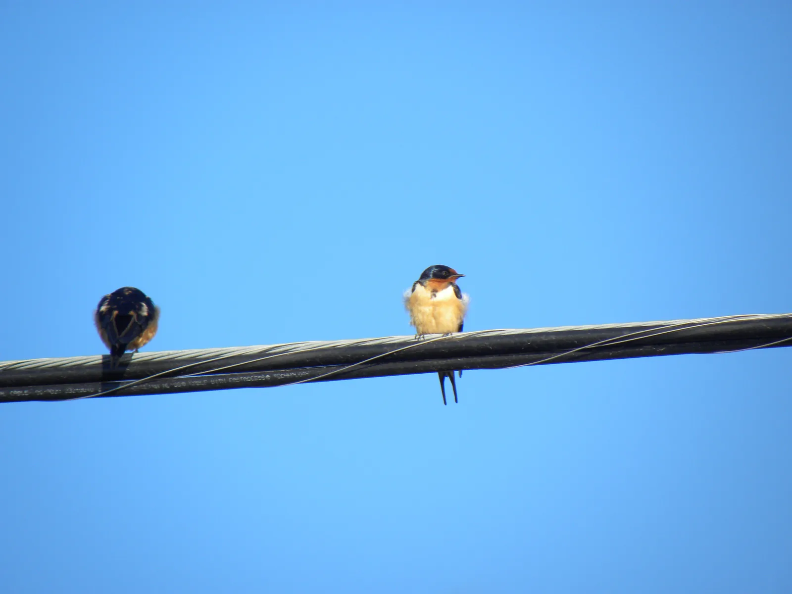
Why can a bird sit on a bare high-voltage wire unharmed, even though a current of hundreds of amperes flows in the wire?
Prior knowledge
- The voltage across the branches of a parallel connection is the same, and the same current passes through every part of a series connectionchapter Resistors in series and in parallel
- The voltage of a resistor is $U = RI$chapter Resistance and Ohm's law
- Voltage tells how much energy per unit of charge changes from one form to anotherchapter Electric circuit, current and voltage
Core path: follow the steps in order. Tasks marked Optional give extra practice. Optional tasks: 4.
Think about it
Small birds sit in a row on the wire of a high-voltage line. A current of hundreds of amperes flows in the wire, and its voltage relative to the ground is tens or hundreds of kilovolts. Still the birds sit calmly, preen their feathers and fly away unharmed. The wire is bare metal, and the birds' feet are right against it.
What decides whether current flows through an object that touches a circuit at two points?
Optional Review: parallel connection
Predict
Make your predictions before investigating 2 questions
Prediction 1: how does the current divide?
Prediction 2: potential at different points of the circuit
Investigate
Change the voltage of the source and the resistors and move the red lead of the meter. Follow the currents, the potentials and the potential graph.
Simulation
How to use
The sliders set the voltage $U$ of the source and the resistors $R_1$, $R_2$ and $R_3$. Measuring point moves the red lead of the voltmeter to the point $A$–$F$ of the wire, and Zero point chooses where the black lead of the meter and the earth symbol are attached. In the picture the potential of each point is a blue number, and the blue shade of a wire is darker the higher the potential is. The purple arrows are the currents in the agreed direction from the positive terminal to the negative terminal. Below is the potential graph of the loop $F$ → source → $A$ → $R_1$ → $B$ → $R_2$ → $E$ → $F$, in which the red dashed line is the potential of the measuring point.
Assumptions of the model
The voltage source is ideal: it has no internal resistance, so the voltage between its terminals is always $U$. The wires have no resistance, and the resistances of the resistors stay constant. The voltmeter draws no current. The numbers are values calculated by the model, not measurements: in a real circuit the wires and the source have a small resistance, so the readings differ slightly.
How the calculation works
The total resistance of the parallel resistors is $R_{23}$, where $\tfrac{1}{R_{23}} = \tfrac{1}{R_2} + \tfrac{1}{R_3}$, and the current of the whole circuit is
$$I_1 = \frac{U}{R_1 + R_{23}}$$
The voltage of the resistor $R_1$ is $U_1 = R_1 I_1$, and by the voltage law the voltage of the branches is $U_2 = U_3 = U - U_1$. The currents of the branches are $I_2 = U_2 : R_2$ and $I_3 = U_3 : R_3$, and their sum is $I_1$. Relative to the negative terminal the potential of the point $A$ is $U$, that of the points $B$ and $C$ is $U - U_1$, and that of the points $D$, $E$ and $F$ is zero. When $B$ is chosen as the zero point, the potential of $B$ is subtracted from all potentials.
Experiment 1: currents at a junction
Test prediction 1. The voltage of the source and the resistors $R_1$ and $R_2$ stay constant; change only the resistor $R_3$. Record the currents for at least two values, for example $30\,\Omega$, $60\,\Omega$ and $120\,\Omega$. On every row calculate $I_2 + I_3$ and compare it with the current $I_1$. Which branch carries the larger current?
Initial state: source voltage $U$ = $9\,\text{V}$, resistor $R_1$ = $10\,\Omega$, resistor $R_2$ = $30\,\Omega$, resistor $R_3$ = $60\,\Omega$, measuring point: point A, zero point: source's negative terminal. Kept constant: source voltage $U$, resistor $R_1$, resistor $R_2$. Varied: resistor $R_3$.
| resistor $R_3$ | $I_1$ $(\text{A})$ | $I_2$ $(\text{A})$ | $I_3$ $(\text{A})$ |
|---|
Experiment 2: a round trip with the potential meter
Test prediction 2. The zero point is the negative terminal of the source, and the values of the circuit stay constant; move only the measuring point. Record the potential at at least three points, preferably at all the points $A$–$F$. At which points is the reading the same, and where does it change?
Initial state: source voltage $U$ = $9\,\text{V}$, resistor $R_1$ = $10\,\Omega$, resistor $R_2$ = $30\,\Omega$, resistor $R_3$ = $60\,\Omega$, measuring point: point A, zero point: source's negative terminal. Kept constant: source voltage $U$, resistor $R_1$, resistor $R_2$, resistor $R_3$, zero point. Varied: measuring point.
| measuring point | $V$ $(\text{V})$ |
|---|
Optional Experiment 3: move the zero point
The values of the circuit stay constant; change only the zero point. Record the potentials of the points $A$, $B$ and $F$ and the voltage of the resistor $R_1$ with each zero point. What changes and what does not?
Initial state: source voltage $U$ = $9\,\text{V}$, resistor $R_1$ = $10\,\Omega$, resistor $R_2$ = $30\,\Omega$, resistor $R_3$ = $60\,\Omega$, measuring point: point A, zero point: source's negative terminal. Kept constant: source voltage $U$, resistor $R_1$, resistor $R_2$, resistor $R_3$, measuring point. Varied: zero point.
| zero point | $V_\text{A}$ $(\text{V})$ | $V_\text{B}$ $(\text{V})$ | $V_\text{F}$ $(\text{V})$ | $U_1$ $(\text{V})$ |
|---|
Conclusion: currents and potentials
Based on your tables, write: what is the relationship between the currents $I_1$, $I_2$ and $I_3$ on every row, and which branch carries the larger current? At which points of the circuit does the potential change, and how large are the changes in total?
Model answer
On every row $I_2 + I_3 = I_1$; for example, when $R_3 = 60\,\Omega$, the currents are $0.20\,\text{A} + 0.10\,\text{A} = 0.30\,\text{A}$. The current arriving at the junction divides among the branches, and no current disappears or appears. The branch with the smaller resistance carries the larger current, because the voltage across the branches is the same. The potential was $9.0\,\text{V}$ after the positive terminal ($A$), $6.0\,\text{V}$ at the points $B$ and $C$ and $0\,\text{V}$ at the points $D$, $E$ and $F$: it stayed the same at the points of the same wire and changed only in the source and the resistors. In the source the potential rose by $9.0\,\text{V}$, and in the resistors it dropped by the same amount in total, $3.0\,\text{V} + 6.0\,\text{V}$. The values are calculated by the model: in the model the wires and the source have no resistance.
Assess your own answer
Tick the points your own answer already contains.
Review the theory summary and practise with the exercises.
Theory summary
Key idea
Current is not used up: Kirchhoff's current law
Electric current is the motion of charges. Charge is neither created nor destroyed, and it does not collect in the wires when the currents stay constant. Therefore all the charge that arrives at a junction, a point where a wire divides into branches, also leaves it. The sum of the currents arriving at a junction is equal to the sum of the currents leaving it. This is Kirchhoff's current law. For the same reason the current is equal on both sides of a resistor: in a resistor electrical energy changes into internal energy of the resistor, which is transferred to the surroundings as heat, but the current is not used up in it.
The voltage across parallel branches is the same (chapter Resistors in series and in parallel), so by Ohm's law the branch with the smaller resistance carries the larger current. In the figure the current in the $30\,\Omega$ branch is twice the current in the $60\,\Omega$ branch, and the branch currents $0.20\,\text{A}$ and $0.10\,\text{A}$ are together equal to the arriving current $0.30\,\text{A}$.
Potential: the electrical level of every point
Every point of a circuit has a potential $V$: the voltage of the point relative to a chosen zero point. The zero point is often chosen to be the negative terminal of the voltage source or the earth, and its potential is $0\,\text{V}$. The voltage between two points is the difference of their potentials. Potential can be compared with height: height depends on where it is measured from, but the difference in height between two points does not. In the same way, moving the zero point changes all potentials by the same amount, but the voltages stay the same.
Potential changes only in the source and in the resistors. In the source it rises from the negative terminal to the positive terminal by the voltage of the source; in this chapter the source is ideal, that is, the effect of its own resistance is neglected. In a resistor it drops in the direction of the current by the voltage $U = RI$. The resistance of a wire is so small that its voltage is neglected, so all points of the same wire have the same potential. In the circuit of the figure the points $B$ and $C$ are the same wire, so the potential of both is $6.0\,\text{V}$.
A round trip in a loop: Kirchhoff's voltage law
A loop is a closed path in a circuit that returns to its starting point. When a loop is traversed, the potential returns to the same value from which it started. Therefore the sum of the rises and drops of potential in a loop is zero. This is Kirchhoff's voltage law. In a circuit of one loop the voltage of the source is equal to the sum of the voltages of the resistors. In terms of energy, voltage tells how much energy per unit of charge changes from one form to another (chapter Electric circuit, current and voltage): a charge gains energy in the source and gives up the same amount in the resistors.
The circuit of the figure has two loops, one through the resistor $R_2$ and the other through the resistor $R_3$. In each of them the $9.0\,\text{V}$ of the source divides into the voltage $3.0\,\text{V}$ of the resistor $R_1$ and the voltage $6.0\,\text{V}$ of the branch. This is why the voltage across parallel branches is the same.
A bird on a wire
The bird's feet are at two points of the same wire, only a few centimetres apart. The bird is a branch parallel to the piece of wire between its feet, whose resistance is negligible. Therefore the voltage between the feet is only millivolts, and by Ohm's law a negligible current flows through the bird. By the current law almost all the current thus continues along the wire. The potential of the bird relative to the ground is high, but danger would arise only if it touched another wire or a pylon at the same time, since their potential is different. For a person the situation is not comparable: a high-voltage line must not be approached, because an electric arc can form even without contact.
Kirchhoff's laws
Kirchhoff's current law for a junction:
$$\sum I_\text{in} = \sum I_\text{out}$$
where $I_\text{in}$ are the currents arriving at the junction (A) and $I_\text{out}$ the currents leaving it (A). For a current dividing into two branches $I_1 = I_2 + I_3$.
The voltage between the points $A$ and $B$ is the difference of the potentials:
$$U_{AB} = V_A - V_B$$
where $U_{AB}$ is the voltage (V) and $V_A$ and $V_B$ are the potentials of the points (V) relative to the same zero point. The voltage is positive when $A$ is at the higher potential.
Kirchhoff's voltage law for a loop:
$$\sum \Delta V = 0$$
where $\Delta V$ (V) is the change of potential in each part of the loop when the loop is traversed once. In the source from the negative terminal to the positive terminal $\Delta V = +U$, in a resistor in the direction of the current $\Delta V = -RI$, and in a wire $\Delta V = 0$. In a circuit of one loop with two resistors the law gives $U - R_1 I - R_2 I = 0$, that is, $U = R_1 I + R_2 I$.
A potential graph shows the potential at different points of a loop. In the graph the loop of the circuit marked with the points $A$–$F$ is traversed from the negative terminal $F$ through the resistors $R_1$ and $R_2$ back to the point $F$. The rise of the source $+9.0\,\text{V}$ is equal to the total of the drops of the resistors $-3.0\,\text{V}$ and $-6.0\,\text{V}$, and in the wires the graph is horizontal.
Common misconception
Many think that a resistor uses up current, so that the current after the resistor would be smaller than before it. A resistor changes electrical energy into its internal energy, but no charges disappear: an ammeter shows the same reading on both sides of a resistor. In a resistor the potential decreases, not the current.
Another common mistake is to use the voltage of the source when calculating the current of a branch. If in the example above one calculated $I_3 = 12\,\text{V} : 30\,\Omega = 0.40\,\text{A}$, more current would leave into the branches in total than arrives at the junction. The voltage of a branch is the voltage of the source minus the voltages of the resistors connected in series with it, here $6.0\,\text{V}$. A third mistake is to think that voltage is a property of a single point: voltage is always the potential difference between two points.
Summary
- Kirchhoff's current law: the sum of the currents arriving at a junction is equal to the sum of the currents leaving it, because charge is conserved. Current is not used up in a resistor.
- Potential $V$ is the voltage of a point relative to the zero point. Voltage is a potential difference $U_{AB} = V_A - V_B$, and it does not depend on the choice of the zero point.
- Potential rises in the source from the negative terminal to the positive terminal, drops in a resistor in the direction of the current by $RI$, and stays the same in a wire.
- Kirchhoff's voltage law: the sum of the changes of potential in a loop is zero, $\sum \Delta V = 0$. Therefore the voltage of the source is shared among the resistors of the loop, and the voltage across parallel branches is the same.
Optional Return to your predictions
Compare your predictions with the values of the model in the experiments and with Kirchhoff's laws. Then return to the question at the start: why does no significant current flow through a bird sitting on a wire, even though the potential of the wire relative to the ground is high?
Would you change your prediction?
Apply
Worked example
Problem
The voltage of a voltage source is $12\,\text{V}$. From the positive terminal of the source the current flows through a resistor $R_1 = 20\,\Omega$ to a junction $B$, from which two parallel branches leave: a resistor $R_2 = 60\,\Omega$ and a resistor $R_3 = 30\,\Omega$. The branches return to the negative terminal of the source, which is the zero point. What is the potential of the point $B$, and how large is the current through the resistor $R_3$?
Step 1/7
Given and find. $U = 12\,\text{V}$, $R_1 = 20\,\Omega$, $R_2 = 60\,\Omega$, $R_3 = 30\,\Omega$ and the potential of the negative terminal $0\,\text{V}$. We are asked for the potential $V_B$ of the point $B$ and the current $I_3$.
Step 2/7
Principle. The whole current $I_1$ flows through the source and the resistor $R_1$. The parallel resistors are replaced with a single resistor $R_{23}$, and then Ohm's law gives $I_1$. By the voltage law the potential drops from the value $U$ of the positive terminal in the resistor $R_1$ by the voltage $R_1 I_1$. The resistor $R_3$ is between the point $B$ and the zero point, so its voltage is $V_B$.
Step 3/7
Formula solved.
$$\begin{aligned} \frac{1}{R_{23}} &= \frac{1}{R_2} + \frac{1}{R_3} \\ I_1 &= \frac{U}{R_1 + R_{23}} \\ V_B &= U - R_1 I_1 \\ I_3 &= \frac{V_B}{R_3} \end{aligned}$$
Step 4/7
Unit conversions. Not needed: all quantities are in base units, and $1\,\text{V} : 1\,\Omega = 1\,\text{A}$.
Step 5/7
Substitution. $$\begin{aligned} \frac{1}{R_{23}} &= \frac{1}{60\,\Omega} + \frac{1}{30\,\Omega} \\ R_{23} &= 20\,\Omega \\ I_1 &= \frac{12\,\text{V}}{20\,\Omega + 20\,\Omega} = 0.30\,\text{A} \\ V_B &= 12\,\text{V} - 20\,\Omega \cdot 0.30\,\text{A} \\ \phantom{V_B} &= 6.0\,\text{V} \\ I_3 &= \frac{6.0\,\text{V}}{30\,\Omega} = 0.20\,\text{A} \end{aligned}$$
Step 6/7
Result. The potential of the point $B$ is $6.0\,\text{V}$, and a current of $0.20\,\text{A}$ flows through the resistor $R_3$. The results are given to two significant figures like the resistances.
Step 7/7
Reasonableness. A current of $6.0\,\text{V} : 60\,\Omega = 0.10\,\text{A}$ flows through the resistor $R_2$, and the branch currents are together $0.30\,\text{A}$, as the current law requires. In the loop $12\,\text{V} - 6.0\,\text{V} - 6.0\,\text{V} = 0$, as the voltage law requires. The branch with the smaller resistance carries the larger current, as it should.
Find the error
Apply to a new situation
A small bird sits on a high-voltage wire, and the distance between its feet is $4.0\,\text{cm}$. A current of $400\,\text{A}$ flows in the wire, and the resistance of the conductor is $0.12\,\Omega$ per kilometre.
How large is the voltage between the bird's feet? Assume that almost all the current flows along the conductor. Give the answer in millivolts.
Hint 1: a guiding question
The voltage between the bird's feet is the same as the voltage of the piece of conductor between the feet. How long is that piece, and what is its resistance?
Hint 2: what is the connection
The resistance of the piece is $0.12\,\Omega$ divided by a kilometre and multiplied by the length of the piece. Convert both $1\,\text{km} = 1000\,\text{m}$ and $4.0\,\text{cm} = 0.040\,\text{m}$.
Hint 3: an intermediate step
and the voltage is $U = RI$.
Show the solution
Given
current $I = 400\,\text{A}$, resistance of the conductor $0.12\,\Omega$ per kilometre, distance between the feet $l = 4.0\,\text{cm}$
Find
the voltage $U$ between the feet in millivolts
Principle
The bird and the piece of conductor between its feet are parallel branches between the same two points, so the voltage across them is the same. The resistance of the piece is negligible compared with the resistance of the bird, so by Ohm's law a negligible current flows through the bird, and by the current law almost all the current continues along the piece. Ohm's law gives the voltage of the piece.
Formula
the resistance of the piece
$U = RI$, so
Conversions
and finally $1\,\text{V} = 1000\,\text{mV}$.
Substitution
Answer
$1.9\,\text{mV}$
Two significant figures like the resistance $0.12\,\Omega$ and the distance between the feet $4.0\,\text{cm}$.
Reasonableness
Over a kilometre the voltage would be $0.12\,\Omega \cdot 400\,\text{A} = 48\,\text{V}$, and $4\,\text{cm}$ is the $25\,000$th part of that: $48\,\text{V} : 25\,000 \approx 2\,\text{mV}$. Such a small voltage does not drive a significant current through the bird's body, even though the potential of the wire relative to the ground is tens or hundreds of kilovolts.
Check your understanding
Exit ticket
Answer on your own first and only then open the answer.
- A current of $0.50\,\text{A}$ arrives at a junction. Two branches leave the junction, and the current in one of them is $0.35\,\text{A}$. How large is the current in the other branch?
Answer
By the current law the sum of the leaving currents is $0.50\,\text{A}$, so the current in the other branch is $0.50\,\text{A} - 0.35\,\text{A} = 0.15\,\text{A}$.
- A series connection has a $9.0\,\text{V}$ voltage source and three resistors. The voltages of two resistors are $2.0\,\text{V}$ and $3.5\,\text{V}$. How large is the voltage of the third resistor?
Answer
By the voltage law the voltages of the resistors are together the voltage of the source, so the voltage of the third resistor is $9.0\,\text{V} - 2.0\,\text{V} - 3.5\,\text{V} = 3.5\,\text{V}$.
1. Concept
2. Moving the zero point
The point $A$ is on the wire of the positive terminal of the source and the point $B$ after the resistor $R_1$. When the zero point is the negative terminal of the source, the potential of the point $A$ is $9.0\,\text{V}$ and the potential of the point $B$ is $6.0\,\text{V}$. After that the point $B$ is chosen as the zero point.
What is the potential of the point $A$ now? Give the answer in volts.
Hint 1: a guiding question
Does the voltage between the points $A$ and $B$ change when the zero point moves?
Hint 2: what is the connection
In the new choice $V_B = 0$, and $V_A - V_B$ is the same voltage as before.
Hint 3: an intermediate step
$U_{AB} = 9.0\,\text{V} - 6.0\,\text{V}$, so $V_A = 0 + U_{AB}$.
Show the solution
Given
relative to the negative terminal $V_A = 9.0\,\text{V}$ and $V_B = 6.0\,\text{V}$; the new zero point is $B$
Find
the potential $V_A'$ of the point $A$ in volts when $V_B' = 0$
Principle
Voltage is the difference between the potentials of two points, and it does not depend on the choice of the zero point. Moving the zero point changes all potentials by the same amount.
Formula
$V_A' - V_B' = V_A - V_B$, from which $V_A' = V_B' + V_A - V_B$
Conversions
Not needed: the potentials are in volts.
Substitution
Answer
$3.0\,\text{V}$
To one decimal place like the given potentials.
Reasonableness
When the old value of $B$, $6.0\,\text{V}$, is subtracted from all potentials, $B$ gets the value $0$ and $A$ the value $3.0\,\text{V}$. The potential of the negative terminal of the source is now $-6.0\,\text{V}$, and the voltage between the terminals is still $3.0\,\text{V} - (-6.0\,\text{V}) = 9.0\,\text{V}$.
Suggestion: one answer does not show everything you can do, but review the theory summary and do the core exercises.
Optional 3. Explain the potential graph
Explain what the rise, the drop and the horizontal part of a potential graph tell about a circuit.
Why does the graph end at the same value from which it started, when the loop has been traversed once?
Model answer
The rise is at the voltage source: in the source the potential rises from the negative terminal to the positive terminal by the voltage of the source, and the charges gain energy. The drop is at a resistor: in the direction of the current the potential drops by the voltage $RI$, and electrical energy changes into internal energy of the resistor. The horizontal part is a wire whose resistance is neglected, so all its points have the same potential. When the loop has been traversed, we are at the same point as at the start, and one point has only one potential. Therefore the rises and drops are together zero: this is Kirchhoff's voltage law.
Assess your own answer
Tick the points your own answer already contains.
Review the theory summary and practise with the exercises.
Exercises
Level 1 · basic practice 5 exercises
One formula or one step of reasoning. Core exercises first, the rest is extra practice.
- Exercise 5-1Core
The wiring of a bicycle's lights has a junction. Two wires arrive at it, with currents $2.4\,\text{A}$ and $0.6\,\text{A}$. Two wires leave the junction, and the current in one of them is $1.8\,\text{A}$.
How large is the current in the other wire leaving?
Answer
$1.2\,\text{A}$
Show the solution
Given
arriving currents $2.4\,\text{A}$ and $0.6\,\text{A}$, leaving current $1.8\,\text{A}$
Find
the current $I$ of the other leaving wire in amperes
Principle
Kirchhoff's current law: charge neither disappears nor collects at the junction, so the sum of the arriving currents is equal to the sum of the leaving currents.
Formula
$I_\text{in1} + I_\text{in2} = I_\text{out1} + I$, from which $I = I_\text{in1} + I_\text{in2} - I_\text{out1}$
Conversions
Not needed: all the currents are in amperes.
Substitution
$I$$= 2.4\,\text{A} + 0.6\,\text{A} - 1.8\,\text{A}$$= 1.2\,\text{A}$Answer
$1.2\,\text{A}$
To one decimal place like the given currents.
Reasonableness
A total of $3.0\,\text{A}$ arrives at the point, and the leaving currents $1.8\,\text{A}$ and $1.2\,\text{A}$ are together the same $3.0\,\text{A}$. The current is positive, so it really does leave the point.
- Exercise 5-2Core
Two resistors connected in series are attached to a voltage source whose voltage is $12.0\,\text{V}$. The voltage of the first resistor is $4.5\,\text{V}$.
How large is the voltage of the second resistor?
Answer
$7.5\,\text{V}$
Show the solution
Given
voltage of the source $U = 12.0\,\text{V}$, voltage of the first resistor $U_1 = 4.5\,\text{V}$
Find
the voltage $U_2$ of the second resistor in volts
Principle
Kirchhoff's voltage law: when a loop is traversed, the sum of the changes of potential is zero. The rise in the source is equal to the total of the drops in the resistors.
Formula
$U - U_1 - U_2 = 0$, from which $U_2 = U - U_1$
Conversions
Not needed: the voltages are in volts.
Substitution
$U_2$$= 12.0\,\text{V} - 4.5\,\text{V}$$= 7.5\,\text{V}$Answer
$7.5\,\text{V}$
To one decimal place like the given voltages.
Reasonableness
$4.5\,\text{V} + 7.5\,\text{V} = 12.0\,\text{V}$, the whole voltage of the source. The voltage of the second resistor is greater, so its resistance is greater, because the current of resistors in series is the same.
- Exercise 5-3
The potential of the point $A$ of a circuit is $5.0\,\text{V}$ and the potential of the point $B$ is $-3.0\,\text{V}$ relative to the same zero point.
How large is the voltage $U_{AB}$?
Answer
$8.0\,\text{V}$
Show the solution
Given
$V_A = 5.0\,\text{V}$, $V_B = -3.0\,\text{V}$ relative to the same zero point
Find
the voltage $U_{AB}$ in volts
Principle
Voltage is the difference of the potentials of two points. When both potentials are given relative to the same zero point, the difference does not depend on the zero point.
Formula
$U_{AB} = V_A - V_B$
Conversions
Not needed: the potentials are in volts.
Substitution
$U_{AB}$$= 5.0\,\text{V} - (-3.0\,\text{V})$$= 8.0\,\text{V}$Answer
$8.0\,\text{V}$
To one decimal place like the potentials.
Reasonableness
The point $A$ is $5.0\,\text{V}$ above the zero point and the point $B$ is $3.0\,\text{V}$ below it, so their difference is $5.0\,\text{V} + 3.0\,\text{V}$. The voltage is positive because $A$ is at the higher potential.
- Exercise 5-4
The resistance of a resistor is $40\,\Omega$, and a current of $0.15\,\text{A}$ flows through it.
By how much does the potential drop in the resistor in the direction of the current?
Answer
$6.0\,\text{V}$
Show the solution
Given
$R = 40\,\Omega$, $I = 0.15\,\text{A}$
Find
the drop of potential in the resistor, that is, the voltage $U$ of the resistor in volts
Principle
In a resistor the potential drops in the direction of the current by the voltage of the resistor, and by Ohm's law the voltage is resistance times current.
Formula
$U = RI$
Conversions
Not needed: $1\,\Omega \cdot 1\,\text{A} = 1\,\text{V}$.
Substitution
$U$$= 40\,\Omega \cdot 0.15\,\text{A}$$= 6.0\,\text{V}$Answer
$6.0\,\text{V}$
Two significant figures like the resistance and the current.
Reasonableness
The estimates $40\,\Omega \cdot 0.1\,\text{A} = 4\,\text{V}$ and $40\,\Omega \cdot 0.2\,\text{A} = 8\,\text{V}$ put $6\,\text{V}$ between them. A drop of $6\,\text{V}$ is smaller than the voltage of a typical battery or mains adapter ($9\,\text{V}$ or $12\,\text{V}$), so the resistor can be in such a circuit, and $\Omega \cdot \text{A} = \text{V}$ gives the right unit.
- Exercise 5-5
The graph shows the potential at different points of the loop of a series connection when the negative terminal of the source is the zero point. The circuit has a source and three resistors.
How large is the voltage of the resistor $R_2$? Read the values you need from the graph.
Answer
$4.0\,\text{V}$
Show the solution
Given
the potentials of the graph at the points of the loop; the zero point is the negative terminal of the source
Find
the voltage $U_2$ of the resistor $R_2$ in volts
Principle
The voltage of a resistor is the potential difference between its ends. The resistor $R_2$ is between the points $B$ and $C$, so its voltage is the drop of potential from the point $B$ to the point $C$.
Reading the graph
At the point $B$ the potential is on the horizontal line at the $7\,\text{V}$ grid line and at the point $C$ at the $3\,\text{V}$ grid line. At the resistor $R_2$ the line drops between these.
Formula
$U_2 = V_B - V_C$
Conversions
Not needed: the potentials are read in volts.
Substitution
$U_2$$= 7.0\,\text{V} - 3.0\,\text{V}$$= 4.0\,\text{V}$Answer
$4.0\,\text{V}$
To two significant figures. The values are read from the $1\,\text{V}$ grid lines.
Reasonableness
The voltages of the resistors are $2\,\text{V}$, $4\,\text{V}$ and $3\,\text{V}$, together $9\,\text{V}$, as much as the rise in the source. The voltage law holds.
Level 2 · applied practice 4 exercises
Two steps, working with measured data, a unit conversion or rearranging a formula. Core exercises first, the rest is extra practice.
- Exercise 5-6Core
The resistance of a resistor is $220\,\Omega$, and a current of $25\,\text{mA}$ flows through it. The current enters the resistor from the point $A$, whose potential is $9.0\,\text{V}$, and leaves it to the point $B$.
What is the potential of the point $B$?
Answer
$3.5\,\text{V}$
Show the solution
Given
$R = 220\,\Omega$, $I = 25\,\text{mA}$, $V_A = 9.0\,\text{V}$; the current flows from the point $A$ to the point $B$
Find
the potential $V_B$ of the point $B$ in volts
Principle
In a resistor the potential drops in the direction of the current by the voltage $RI$ given by Ohm's law. The point $B$ is after the resistor, so its potential is smaller than that of the point $A$.
Formula
$V_A - V_B = RI$, from which $V_B = V_A - RI$
Conversions
$I$$= 25\,\text{mA}$$= 25 \cdot 0.001\,\text{A}$$= 0.025\,\text{A}$Substitution
$V_B$$= 9.0\,\text{V} - 220\,\Omega \cdot 0.025\,\text{A}$$= 9.0\,\text{V} - 5.5\,\text{V}$$= 3.5\,\text{V}$Answer
$3.5\,\text{V}$
To one decimal place like the potential $9.0\,\text{V}$.
Reasonableness
The potential drops in the resistor, and $3.5\,\text{V}$ is smaller than $9.0\,\text{V}$. Without converting the milliamperes the drop would be $5500\,\text{V}$, which is impossible in a $9\,\text{V}$ circuit.
- Exercise 5-7Core
Resistors of $200\,\Omega$ and $400\,\Omega$ are connected in series to a voltage source whose voltage is $12.0\,\text{V}$. The positive terminal of the source is connected to the $200\,\Omega$ resistor and the negative terminal, which is the zero point, to the $400\,\Omega$ resistor.
What is the potential of the wire between the resistors?
Answer
$8.0\,\text{V}$
Show the solution
Given
$U = 12.0\,\text{V}$, $R_1 = 200\,\Omega$ (on the side of the positive terminal), $R_2 = 400\,\Omega$ (on the side of the negative terminal); the negative terminal is the zero point
Find
the potential $V$ of the wire between the resistors in volts
Principle
In a series connection the same current flows through both resistors, and the total resistance is the sum of the resistances. Between the middle wire and the negative terminal there is only the resistor $R_2$, so the potential of the middle wire is the voltage of the resistor $R_2$.
Formula
$I = \dfrac{U}{R_1 + R_2}$ and $V = R_2 I$, so $V = \dfrac{R_2 U}{R_1 + R_2}$
Conversions
Not needed: $1\,\text{V} : 1\,\Omega = 1\,\text{A}$.
Substitution
$I$$= \dfrac{12.0\,\text{V}}{200\,\Omega + 400\,\Omega}$$= 0.020\,\text{A}$$V$$= 400\,\Omega \cdot 0.020\,\text{A}$$= 8.0\,\text{V}$Answer
$8.0\,\text{V}$
Two significant figures, because the resistances are given to two figures.
Reasonableness
The voltage of the resistor $R_1$ is $200\,\Omega \cdot 0.020\,\text{A} = 4.0\,\text{V}$, and $4.0\,\text{V} + 8.0\,\text{V} = 12.0\,\text{V}$. The larger resistor gets the larger share of the voltage, as it should in a series connection.
- Exercise 5-8
In the circuit of the figure two resistors are connected in parallel to a voltage source.
What is the reading of the ammeter in the main wire? The resistances of the source and the wires are neglected.
Answer
$0.50\,\text{A}$
Show the solution
Given
from the figure $U = 6.0\,\text{V}$, parallel resistors $R_2 = 20\,\Omega$ and $R_3 = 30\,\Omega$
Find
the current $I$ of the main wire in amperes
Principle
Each branch forms with the source a loop that has no other resistors, so by the voltage law the voltage of each resistor is the voltage of the source. By the current law the current of the main wire is the sum of the currents of the branches.
Formula
$I_2 = \dfrac{U}{R_2}$, $I_3 = \dfrac{U}{R_3}$ and $I = I_2 + I_3$, so $I = \dfrac{U}{R_2} + \dfrac{U}{R_3}$
Conversions
Not needed: $1\,\text{V} : 1\,\Omega = 1\,\text{A}$.
Substitution
$I$$= \dfrac{6.0\,\text{V}}{20\,\Omega} + \dfrac{6.0\,\text{V}}{30\,\Omega}$$= 0.30\,\text{A} + 0.20\,\text{A}$$= 0.50\,\text{A}$Answer
$0.50\,\text{A}$
Two significant figures like the initial data.
Reasonableness
The total resistance of the parallel connection is $12\,\Omega$, and $6.0\,\text{V} : 12\,\Omega = 0.50\,\text{A}$ gives the same result. The branch with the smaller resistance carries the larger current.
- Exercise 5-9
A series connection has a voltage source whose voltage is $9.0\,\text{V}$, a resistor $R_1 = 120\,\Omega$ and an unknown resistor $R_2$. The ammeter shows $50\,\text{mA}$.
What is the resistance of the resistor $R_2$?
Answer
$60\,\Omega$
Show the solution
Given
$U = 9.0\,\text{V}$, $R_1 = 120\,\Omega$, current $I = 50\,\text{mA}$
Find
the resistance $R_2$ in ohms
Principle
In a series connection the same current flows through both resistors. By the voltage law the voltage of the source is shared among the resistors: $U = R_1 I + R_2 I$.
Formula
$U = R_1 I + R_2 I$, from which $R_2 = \dfrac{U - R_1 I}{I}$
Conversions
$I$$= 50\,\text{mA}$$= 50 \cdot 0.001\,\text{A}$$= 0.050\,\text{A}$Substitution
$R_2$$= \dfrac{9.0\,\text{V} - 120\,\Omega \cdot 0.050\,\text{A}}{0.050\,\text{A}}$$= \dfrac{3.0\,\text{V}}{0.050\,\text{A}}$$= 60\,\Omega$Answer
$60\,\Omega$
Two significant figures like the voltage and the current.
Reasonableness
The total resistance $120\,\Omega + 60\,\Omega = 180\,\Omega$ gives the current $9.0\,\text{V} : 180\,\Omega = 0.050\,\text{A}$, which is the measured reading. The voltage $3.0\,\text{V}$ of the resistor $R_2$ is half the voltage of the resistor $R_1$, as the ratio of the resistances requires.
Level 3 · challenging 3 exercises
Optional: application, two ideas together or a new situation where you reason for yourself.
- Exercise 5-10
Three resistors, $R_1 = 30\,\Omega$, $R_2 = 50\,\Omega$ and $R_3 = 40\,\Omega$, are connected in this order in series to a voltage source whose voltage is $12\,\text{V}$: the positive terminal is connected to the resistor $R_1$ and the negative terminal to the resistor $R_3$. The wire between the resistors $R_1$ and $R_2$ is chosen as the zero point.
What is the potential of the negative terminal of the source? Give the answer with its sign.
Answer
$-9.0\,\text{V}$
Show the solution
Given
$U = 12\,\text{V}$, $R_1 = 30\,\Omega$, $R_2 = 50\,\Omega$, $R_3 = 40\,\Omega$ in series; the zero point is between the resistors $R_1$ and $R_2$
Find
the potential $V_-$ of the negative terminal of the source in volts, with its sign
Principle
In a series connection the same current flows through all the resistors. When we go from the zero point in the direction of the current to the negative terminal, the potential drops in the resistors $R_2$ and $R_3$ by their voltages. So the potential of the negative terminal is negative.
Formula
$I = \dfrac{U}{R_1 + R_2 + R_3}$ and $0 - R_2 I - R_3 I = V_-$, so $V_- = -(R_2 + R_3) I$
Conversions
Not needed: $1\,\text{V} : 1\,\Omega = 1\,\text{A}$.
Substitution
$I$$= \dfrac{12\,\text{V}}{30\,\Omega + 50\,\Omega + 40\,\Omega}$$= 0.10\,\text{A}$$V_-$$= -(50\,\Omega + 40\,\Omega) \cdot 0.10\,\text{A}$$= -9.0\,\text{V}$Answer
$-9.0\,\text{V}$
Two significant figures like the voltage $12\,\text{V}$.
Reasonableness
The potential of the positive terminal is $R_1 I = 3.0\,\text{V}$, so the voltage between the terminals of the source is $3.0\,\text{V} - (-9.0\,\text{V}) = 12\,\text{V}$, as it should be. Moving the zero point did not change the voltages, only the values of the potentials.
- Exercise 5-11
In the circuit of the figure the ammeter shows $0.20\,\text{A}$. The resistance of the resistor $R_3$ is not known. What is the resistance of the resistor $R_3$?
Answer
$30\,\Omega$
Show the solution
Given
from the figure $U = 12\,\text{V}$, $R_1 = 40\,\Omega$, $R_2 = 60\,\Omega$, current of the main wire $I_1 = 0.20\,\text{A}$
Find
the resistance $R_3$ in ohms
Principle
The whole current flows through the resistor $R_1$. By the voltage law the common voltage of the branches is the voltage of the source minus the voltage of the resistor $R_1$. By the current law the current of the resistor $R_3$ is the current of the main wire minus the current of the resistor $R_2$, and Ohm's law gives the resistance.
Formula
$U_{23} = U - R_1 I_1$, $I_3 = I_1 - \dfrac{U_{23}}{R_2}$ and $R_3 = \dfrac{U_{23}}{I_3}$
Conversions
Not needed: all quantities are in base units.
Substitution
$U_{23}$$= 12\,\text{V} - 40\,\Omega \cdot 0.20\,\text{A}$$= 4.0\,\text{V}$$I_3$$= 0.20\,\text{A} - \dfrac{4.0\,\text{V}}{60\,\Omega}$$= 0.1333\,\text{A}$$R_3$$= \dfrac{4.0\,\text{V}}{0.1333\,\text{A}}$$= 30.0\,\Omega$Answer
$30\,\Omega$
Two significant figures like the current $0.20\,\text{A}$.
Reasonableness
The total resistance of the parallel connection of $60\,\Omega$ and $30\,\Omega$ is $20\,\Omega$, and the $40\,\Omega + 20\,\Omega = 60\,\Omega$ of the whole circuit gives the current $12\,\text{V} : 60\,\Omega = 0.20\,\text{A}$, which is the reading of the meter. The current of the resistor $R_3$ is twice the current of the resistor $R_2$, because its resistance is half.
- Exercise 5-12
A parallel connection of two identical bulbs is connected to a voltage source whose voltage is $12\,\text{V}$. A resistor of $20\,\Omega$ is connected between the positive terminal of the source and the bulbs.
The resistance of each bulb is $60\,\Omega$, and it is assumed to stay constant. The resistances of the source and the wires are neglected. The negative terminal of the source is the zero point.
One of the bulbs is unscrewed from its socket.
By how much does the potential of the junction between the resistor and the bulbs change? Give the answer with its sign (positive if the potential increases).
Answer
$1.8\,\text{V}$
Show the solution
Given
$U = 12\,\text{V}$, a resistor $R = 20\,\Omega$ between the positive terminal and the bulbs, two parallel bulbs, the resistance of each $R_\text{L} = 60\,\Omega$ (constant); the negative terminal is the zero point
Find
the change $\Delta V$ of the potential of the junction between the resistor and the bulbs in volts, with its sign
Principle
The resistances of the source and the wires are neglected. Between the junction of the resistor and the bulbs and the negative terminal there is the bulb branch, so the potential of the junction is the voltage of the bulbs. By the voltage law it is the voltage of the source minus the voltage $RI$ of the series resistor. When a bulb is removed, the resistance of the branch increases, the current decreases, the voltage of the series resistor decreases and the voltage of the bulb increases.
Formula
$V$$= \dfrac{R_\text{b}}{R + R_\text{b}}\, U$where $R_\text{b}$ is the resistance of the bulb branch; $\Delta V = V_\text{one} - V_\text{two}$
Conversions
Not needed: all quantities are in base units.
Substitution
Two bulbs:
$R_\text{b}$$= 30\,\Omega$$V_\text{two}$$= \dfrac{30\,\Omega}{50\,\Omega} \cdot 12\,\text{V}$$= 7.2\,\text{V}$One bulb:
$R_\text{b}$$= 60\,\Omega$$V_\text{one}$$= \dfrac{60\,\Omega}{80\,\Omega} \cdot 12\,\text{V}$$= 9.0\,\text{V}$$\Delta V$$= 9.0\,\text{V} - 7.2\,\text{V}$$= 1.8\,\text{V}$Answer
$1.8\,\text{V}$
Two significant figures like the resistances.
Reasonableness
The current decreases from $0.24\,\text{A}$ to $0.15\,\text{A}$, so the voltage of the series resistor decreases from $4.8\,\text{V}$ to $3.0\,\text{V}$, that is, by $1.8\,\text{V}$, and the voltage of the bulb increases by exactly that much. The remaining bulb shines brighter, because its voltage increases.
Photographs
- Barn Swallows on Power Line. Mathieu Landretti. source, CC BY-SA 4.0
