
Resistors in series and in parallel
Why do all the bulbs of an old string of fairy lights go out when one bulb breaks, while at home the floor lamp stays on even when the desk lamp is switched off?
Prior knowledge
- The voltage, current and resistance of a resistor are linked by Ohm's law $U = RI$chapter Resistance and Ohm's law
- An ammeter is connected in series and a voltmeter in parallel with the component being measuredchapter Measurements in an electric circuit
- The agreed direction of the current is from the positive terminal of the battery to the negative terminalchapter Electric circuit, current and voltage
Core path: follow the steps in order. Tasks marked Optional give extra practice. Optional tasks: 3.
Think about it
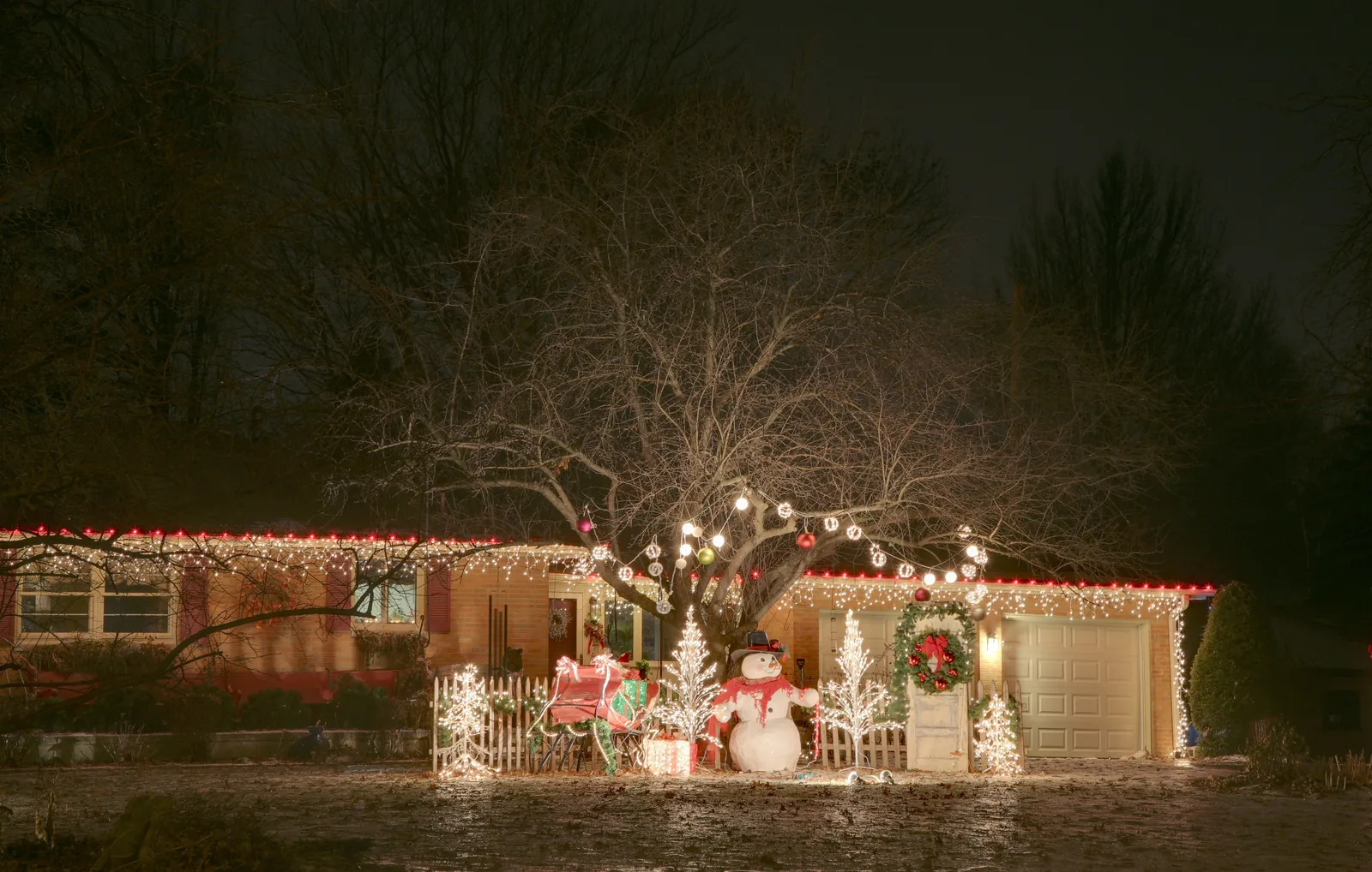
On a December evening an old string of fairy lights hangs in a window. All its bulbs went out at the same moment when one small bulb came loose from its socket. The floor lamp and the desk lamp plugged into the same extension cord are still on, though, and either of them can be switched off independently of the other.
How does the way the lamps are connected decide which lamps stop carrying current when one lamp goes out?
Optional Recall: Ohm's law
Predict
Make your predictions before investigating 2 questions
Prediction 1: series connection
Prediction 2: parallel connection
Investigate
Connect the resistors in series or in parallel and see how the current and the voltages are shared and how large a current leaves the battery.
Simulation
How to use
Choose the Connection: one resistor, two resistors in series or two resistors in parallel. Adjust the battery voltage $U$ and the resistors $R_1$ and $R_2$. The ammeter $\text{A}$ shows the current $I$ leaving the battery. Next to the resistors you can see their voltages and, in the parallel connection, the branch currents. The speed of the purple dots shows the size of the current in each part of the wire. The more power is transformed into internal energy in a resistor, the more orange it glows. Speed changes only the pace of the dots' motion, not the readings.
Assumptions of the model
The battery is ideal: the voltage $U$ between its terminals stays the same whatever the current. The resistance of the wires and the ammeter is zero, and the resistances of the resistors do not change as they warm up. All readings are values calculated by the model, not measurements. The dots show the agreed direction of the current from the positive terminal to the negative terminal; in a metal wire the electrons move in the opposite direction. The speed of the dots is only an illustration: the real average motion of the electrons in a wire is very slow.
How the calculation works
In a series connection $R = R_1 + R_2$ and the same current $I = U : R$ passes through the whole circuit. The voltages of the resistors are $U_1 = R_1 I$ and $U_2 = R_2 I$.
In a parallel connection the battery voltage $U$ is across both resistors, so the branch currents are $I_1 = U : R_1$ and $I_2 = U : R_2$. The current leaving the battery is $I = I_1 + I_2$ and the total resistance is $R = U : I$, which is the same as
$$R = \frac{R_1 R_2}{R_1 + R_2}$$
The glow of a resistor follows the power $P = UI$, which is covered in the chapter Electric power and the heating of a resistor.
Experiment 1: series connection
Test prediction 1. The resistors are in series, the battery voltage is $6.0\,\text{V}$ and $R_1 = 100\,\Omega$. Change only the resistor $R_2$ and record the currents and voltages for at least two values, for example $50\,\Omega$, $100\,\Omega$ and $200\,\Omega$. Compare the currents $I_1$ and $I_2$ and calculate the sum of the voltages.
Initial state: connection: series connection, battery voltage = $6\,\text{V}$, $R_1$: $100\,\Omega$, $R_2$: $50\,\Omega$. Kept constant: connection, battery voltage, $R_1$. Varied: $R_2$.
| $R_2$ | $I_1$ $(\text{mA})$ | $I_2$ $(\text{mA})$ | $U_1$ $(\text{V})$ | $U_2$ $(\text{V})$ |
|---|
Experiment 2: parallel connection
Test prediction 2. The resistors are now in parallel, the battery voltage is $6.0\,\text{V}$ and $R_1 = 100\,\Omega$. Change only the resistor $R_2$ and record the currents and the total resistance for at least two values, first the prediction's value $100\,\Omega$ and then for example $200\,\Omega$ and $50\,\Omega$. Does the branch current $I_1$ change when $R_2$ changes? Is the total resistance ever greater than the smaller of the resistors?
Initial state: connection: parallel connection, battery voltage = $6\,\text{V}$, $R_1$: $100\,\Omega$, $R_2$: $100\,\Omega$. Kept constant: connection, battery voltage, $R_1$. Varied: $R_2$.
| $R_2$ | $I_1$ $(\text{mA})$ | $I_2$ $(\text{mA})$ | $I$ $(\text{mA})$ | $R$ $(\Omega)$ |
|---|
Conclusion: current and voltage in the connections
Based on your tables, write: which quantity was the same in both resistors in the series connection, and which was shared between them? Which quantity was the same in both branches in the parallel connection, and how did the current leaving the battery depend on the branch currents? How did the total resistance change when the second resistor was connected in parallel? Finally, state that the numbers are model values and which assumptions they require.
Model answer
In the series connection the current was the same in both resistors, for example $40.0\,\text{mA}$ when $R_2 = 50\,\Omega$ and $20.0\,\text{mA}$ when $R_2 = 200\,\Omega$. The battery voltage was shared between the resistors in proportion to their resistances: $4.00\,\text{V} + 2.00\,\text{V} = 6.0\,\text{V}$. In the parallel connection the battery voltage was across both branches, so the branch current $I_1$ stayed at $60.0\,\text{mA}$ even though $R_2$ changed. The current leaving the battery was the sum of the branch currents, for example $60.0\,\text{mA} + 30.0\,\text{mA} = 90.0\,\text{mA}$. The total resistance was always smaller than the smaller of the resistors, for example $50.0\,\Omega$ with two $100\,\Omega$ resistors. The values are calculated by the model: the battery is ideal and the wires have no resistance.
Assess your own answer
Tick the points your own answer already contains.
Review the theory summary and practise with the exercises.
Theory summary
Key idea
An electric circuit often has more than one resistor or lamp. Two resistors can be connected to a battery in two ways: one after the other in the same loop, that is, in series, or in separate branches between the same two points, that is, in parallel. The way they are connected decides how the current and the voltage are shared between the resistors and how large a current leaves the battery. In this chapter the battery is ideal, that is, the voltage between its terminals does not depend on the current, and the resistance of the wires is ignored.
Series connection
In a series connection the resistors are one after the other, and the charges have only one route. So the same current $I$ passes through every resistor. Current is not used up in a resistor: charge does not vanish or pile up anywhere in the circuit. The voltage across a resistor tells how much of the electrical energy of each charge is transformed into internal energy of the resistor, which is transferred to the surroundings as heat. The battery voltage is shared between the resistors, $U = U_1 + U_2$. By Ohm's law $U_1 = R_1 I$ and $U_2 = R_2 I$, so the larger voltage is across the larger resistance.
If a component connected in series breaks, for example the filament of a lamp burns through, the only route is opened and the current stops in the whole circuit. This is why all the bulbs of an old-style string of fairy lights go out when one of them breaks.
Parallel connection
In a parallel connection the resistors are in separate branches between the same two branching points. The ends of both branches are joined by wires to the terminals of the battery, so the same voltage $U$ is across both resistors. At a branching point the current divides, and at the second branching point the branch currents join again: the current leaving the battery is the sum of the branch currents, $I = I_1 + I_2$. By Ohm's law the branch current is $I_1 = U : R_1$, so a larger current passes through the branch with the smaller resistance.
A new parallel branch does not change the currents of the other branches, because their voltage stays the same. It adds routes to the circuit, so the current leaving the battery increases. The lamps and sockets in homes are connected in parallel: each appliance gets the same mains voltage, and switching one appliance off breaks only its own branch.
Total resistance
A connection of resistors can be replaced with a single resistor from which the battery gives the same current. The resistance of this resistor is the total resistance $R$ of the connection: $U = RI$ holds for it, where $I$ is the current leaving the battery. In a series connection the charges pass through every resistor, so the total resistance is greater than any of the resistors. In a parallel connection each branch is a new route, so the total resistance is smaller than the smallest of the branch resistances.
Total resistance of resistors
In a series connection the voltages add up, $U = U_1 + U_2$, and the same current $I$ passes through every resistor. When the voltages are written using Ohm's law, we get $RI = R_1 I + R_2 I$, and the current $I$ cancels. So the total resistance of resistors connected in series is
$$R = R_1 + R_2 + R_3 + \dots$$
where $R$ is the total resistance ($\Omega$) and $R_1$, $R_2$, $R_3$, … are the resistances of the resistors ($\Omega$).
In a parallel connection the currents add up, $I = I_1 + I_2$, and the same voltage $U$ is across every resistor. When the currents are written using Ohm's law, we get $\tfrac{U}{R} = \tfrac{U}{R_1} + \tfrac{U}{R_2}$, and the voltage $U$ cancels. For the total resistance of resistors connected in parallel
$$\frac{1}{R} = \frac{1}{R_1} + \frac{1}{R_2} + \frac{1}{R_3} + \dots$$
where $R$ is the total resistance and $R_1$, $R_2$, $R_3$, … are the resistances of the branches. The equation first gives the number $\tfrac{1}{R}$, whose unit is $\tfrac{1}{\Omega}$. The total resistance is its reciprocal, so remember to invert at the end of the calculation. For two parallel resistors the equation can be solved in advance:
$$R = \frac{R_1 R_2}{R_1 + R_2}$$
When two equal resistors are connected in parallel, the total resistance is half the resistance of one resistor.
In the graph the resistor $R_1 = 100\,\Omega$ stays the same and $R_2$ changes. The total resistance of the series connection grows by as much as $R_2$ and is always over $100\,\Omega$. The total resistance of the parallel connection always stays smaller than either resistor; when $R_2 = 100\,\Omega$, it is $50\,\Omega$.
Mixed connection
Many circuits have both resistors in series and resistors in parallel. The solution goes step by step, from the inside out:
- Replace the parallel resistors $R_2$ and $R_3$ with a single resistor $R_{23}$ using the formula for a parallel connection.
- The resistor $R_1$ is in series with it, so the total resistance is $R = R_1 + R_{23}$.
- The current leaving the battery is $I = U : R$. It passes through both $R_1$ and the parallel part.
- The voltages of the series parts are obtained from Ohm's law: $U_1 = R_1 I$ and $U_{23} = R_{23} I$. They add up to the battery voltage.
- The voltage $U_{23}$ is the same across both parallel resistors, so the branch currents are $I_2 = U_{23} : R_2$ and $I_3 = U_{23} : R_3$. They add up to the current $I$.
Common misconception
Many people think that current is used up in a resistor, so that the first resistor in a series connection would get the most current and the later ones less. But when $10\,\Omega$ and $20\,\Omega$ resistors are connected in series to a $6.0\,\text{V}$ battery, the same current of $0.20\,\text{A}$ passes through both. No charge is lost in a resistor; instead, the electrical energy of the charges is transformed into internal energy, and in a lamp also into light.
Another common mistake is to think that every added resistor increases the total resistance. This is true only in a series connection. A resistor added in parallel opens a new route, so the total resistance decreases and the current leaving the battery increases.
Summary
- In a series connection the same current passes through every resistor, the voltages add up, $U = U_1 + U_2$, and the total resistance is $R = R_1 + R_2 + \dots$
- In a parallel connection the same voltage is across every branch, the currents add up, $I = I_1 + I_2$, and $\tfrac{1}{R} = \tfrac{1}{R_1} + \tfrac{1}{R_2} + \dots$. The total resistance is smaller than the smallest of the branch resistances.
- When a component connected in series breaks, the current stops in the whole circuit; when a parallel branch breaks, it stops only in that branch.
- The total resistance of a mixed connection is calculated step by step: first the parallel parts, then those connected in series.
Optional Return to your predictions
Compare your predictions with the model values of the experiments. Then return to the opening question: why did all the bulbs of the string of fairy lights go out when one bulb came loose, while the lamps plugged into the extension cord can be switched off independently of each other? Which connection is in the string of lights and which in the extension cord?
Would you change your prediction?
Apply
Worked example
Problem
Two resistors, $R_1 = 120\,\Omega$ and $R_2 = 60\,\Omega$, are connected in parallel to a $9.0\,\text{V}$ battery. How large a current leaves the battery? The battery is considered ideal, and the resistance of the wires is ignored.
Step 1/7
Given and find. $R_1 = 120\,\Omega$, $R_2 = 60\,\Omega$ and $U = 9.0\,\text{V}$. We want the current $I$ leaving the battery.
Step 2/7
Principle. The resistors are in parallel, so the battery voltage is across both. The connection can be replaced with the total resistance $R$, and Ohm's law then gives the current leaving the battery, $I = U : R$.
Step 3/7
Formula solved. We solve $R$ from the equation of the parallel connection, and with it the current $I$:
$$\begin{aligned} \frac{1}{R} &= \frac{1}{R_1} + \frac{1}{R_2} \\[4pt] R &= \frac{R_1 R_2}{R_1 + R_2} \\[4pt] I &= \frac{U}{R} \end{aligned}$$
Step 4/7
Unit conversions. Not needed: the resistances are in ohms and the voltage in volts, and $\tfrac{\text{V}}{\Omega} = \text{A}$.
Step 5/7
Substitution. $$\begin{aligned} R &= \frac{120\,\Omega \cdot 60\,\Omega}{120\,\Omega + 60\,\Omega} \\ &= 40\,\Omega \\[6pt] I &= \frac{9.0\,\text{V}}{40\,\Omega} \\ &= 0.225\,\text{A} \end{aligned}$$
Step 6/7
Result. The current leaving the battery is $0.23\,\text{A}$, or about $230\,\text{mA}$. The result is given to two significant figures like the voltage $9.0\,\text{V}$.
Step 7/7
Reasonableness. The branch currents give the same result: $9.0\,\text{V} : 120\,\Omega = 0.075\,\text{A}$ and $9.0\,\text{V} : 60\,\Omega = 0.15\,\text{A}$, together $0.225\,\text{A}$. The total resistance $40\,\Omega$ is smaller than the smaller of the resistors, $60\,\Omega$, as it should be in a parallel connection.
Find the error
Apply to a new situation
In the circuit in the figure the battery is ideal and the resistance of the wires is ignored.
How large a current leaves the battery? Answer in amperes.
Hint 1: a guiding question
Which resistors are between the same two branching points, and which resistor is on the same route as them, the route that carries the whole current?
Hint 2: what is the connection
First replace the parallel resistors with one resistor: $R_{23} = \dfrac{R_2 R_3}{R_2 + R_3}$. It is in series with the $20\,\Omega$ resistor.
Hint 3: an intermediate step
so $R = 40\,\Omega$ and $I = 12\,\text{V} : 40\,\Omega$.
Show the solution
Given
from the figure, the battery voltage $U = 12\,\text{V}$, the series resistor $R_1 = 20\,\Omega$ and the parallel resistors $R_2 = 60\,\Omega$ and $R_3 = 30\,\Omega$; the battery is ideal and the wires have no resistance
Find
the current $I$ leaving the battery in amperes
Principle
The parallel resistors are replaced with one resistor $R_{23}$, with which the $20\,\Omega$ resistor is in series, because the whole current passes through it. The total resistance is the sum of these, and Ohm's law gives the current leaving the battery.
Reading the figure
From the figure we read $12\,\text{V}$ and the resistors. $60\,\Omega$ and $30\,\Omega$ are between the same two branching points, that is, in parallel, and $20\,\Omega$ is in the same loop as the battery before the branching, that is, in series.
Formula
$R_{23} = \dfrac{R_2 R_3}{R_2 + R_3}$, $R = R_1 + R_{23}$ and $U = RI$, so
$$I = \frac{U}{R_1 + \dfrac{R_2 R_3}{R_2 + R_3}}$$
Conversions
Not needed: the voltage is in volts and the resistances in ohms, and $\tfrac{\text{V}}{\Omega} = \text{A}$.
Substitution
Answer
$0.30\,\text{A}$
Two significant figures like the voltage $12\,\text{V}$.
Reasonableness
Across the series resistor there is $20\,\Omega \cdot 0.30\,\text{A} = 6.0\,\text{V}$ and across the parallel part the remaining $6.0\,\text{V}$. The branch currents are $6.0\,\text{V} : 60\,\Omega = 0.10\,\text{A}$ and $6.0\,\text{V} : 30\,\Omega = 0.20\,\text{A}$, together $0.30\,\text{A}$, the same as the current leaving the battery.
Check your understanding
Exit ticket
Answer on your own first and only then open the answer.
- Resistors $47\,\Omega$ and $68\,\Omega$ are connected in series. How large is their total resistance?
Answer
In a series connection the resistances are added:
$R$$= 47\,\Omega + 68\,\Omega$$= 115\,\Omega$ - Two identical $80\,\Omega$ resistors are connected in parallel. How large is the total resistance, and why is it smaller than the resistance of one resistor?
Answer
$\tfrac{1}{R}$$= \tfrac{1}{80\,\Omega} + \tfrac{1}{80\,\Omega}$$= \tfrac{2}{80\,\Omega}$so $R = 40\,\Omega$. A resistor connected in parallel is a new route: at the same voltage twice the current leaves the battery, so the total resistance is half.
1. Concept
2. Sharing of voltage
Resistors $220\,\Omega$ and $330\,\Omega$ are connected in series to a $9.0\,\text{V}$ battery. How large is the voltage across the $330\,\Omega$ resistor? Answer in volts.
Hint 1: a guiding question
Which quantity is the same in both resistors in a series connection?
Hint 2: what is the connection
First calculate the current using the total resistance: $I = \dfrac{U}{R_1 + R_2}$.
Hint 3: an intermediate step
and $U_2 = 330\,\Omega \cdot I$.
Show the solution
Given
resistors in series $R_1 = 220\,\Omega$ and $R_2 = 330\,\Omega$, battery voltage $U = 9.0\,\text{V}$
Find
the voltage $U_2$ across resistor $R_2$ in volts
Principle
In a series connection the same current passes through both resistors, and it is obtained from the total resistance by Ohm's law. The voltage across a resistor is its resistance times this current.
Formula
$I = \dfrac{U}{R_1 + R_2}$ and $U_2 = R_2 I$, so
$$U_2 = \frac{R_2 U}{R_1 + R_2}$$
Conversions
Not needed: the resistances are in ohms and the voltage in volts.
Substitution
Answer
$5.4\,\text{V}$
Two significant figures like the voltage $9.0\,\text{V}$.
Reasonableness
The share of resistor $R_2$ in the total resistance is $330 : 550 = 0.6$, so $0.6$ of the battery voltage is across it. Across the other resistor there is $9.0\,\text{V} - 5.4\,\text{V} = 3.6\,\text{V}$, and the larger voltage is across the larger resistance.
Suggestion: one answer does not show everything you can do, but review the theory summary and do the core exercises.
Optional 3. Explain
Explain why the total resistance of two resistors connected in parallel is always smaller than the resistance of either resistor. Use voltage and current in your explanation.
Model answer
In a parallel connection the same battery voltage $U$ is across both resistors. Each branch therefore gets the same current it would get alone, for example $I_1 = U : R_1$. The current leaving the battery is the sum of the branch currents, $I = I_1 + I_2$, so it is larger than $I_1$ or $I_2$. The total resistance is $R = U : I$. When the same voltage gives a larger current than either resistor alone, the total resistance is smaller than $R_1$ and smaller than $R_2$. Every new branch is an extra route for the charges.
Assess your own answer
Tick the points your own answer already contains.
Review the theory summary and practise with the exercises.
Exercises
Level 1 · basic practice 5 exercises
One formula or one step of reasoning. Core exercises first, the rest is extra practice.
- Exercise 4-1Core
On the circuit board of an electronics kit there are three resistors in series: $120\,\Omega$, $220\,\Omega$ and $330\,\Omega$. How large is their total resistance?
Answer
$670\,\Omega$
Show the solution
Given
resistors in series $R_1 = 120\,\Omega$, $R_2 = 220\,\Omega$ and $R_3 = 330\,\Omega$
Find
the total resistance $R$ in ohms
Principle
In a series connection the same current passes through every resistor and the voltages of the resistors add up. So the total resistance is the sum of the resistances of the resistors.
Formula
$R = R_1 + R_2 + R_3$
Conversions
Not needed, all the resistances are in ohms.
Substitution
$R$$= 120\,\Omega + 220\,\Omega + 330\,\Omega$$= 670\,\Omega$Answer
$670\,\Omega$
The precision of a sum is decided by the terms, which are all given to the nearest ohm.
Reasonableness
The total resistance of a series connection is greater than the largest of the resistors, $330\,\Omega$. The result is about twice the largest resistor, which fits, because the other two resistors together are $340\,\Omega$.
- Exercise 4-2Core
Resistors $40\,\Omega$ and $60\,\Omega$ are connected in parallel. How large is the total resistance of the connection?
Answer
$24\,\Omega$
Show the solution
Given
resistors in parallel $R_1 = 40\,\Omega$ and $R_2 = 60\,\Omega$
Find
the total resistance $R$ in ohms
Principle
In a parallel connection the same voltage is across both resistors and the branch currents add up. So the reciprocal of the total resistance is the sum of the reciprocals of the branch resistances.
Formula
$\dfrac{1}{R}$$= \dfrac{1}{R_1} + \dfrac{1}{R_2}$so $R = \dfrac{R_1 R_2}{R_1 + R_2}$
Conversions
Not needed, both resistances are in ohms.
Substitution
$R$$= \dfrac{40\,\Omega \cdot 60\,\Omega}{40\,\Omega + 60\,\Omega}$$= \dfrac{2400\,\Omega^2}{100\,\Omega}$$= 24\,\Omega$Answer
$24\,\Omega$
Two significant figures like the values of the resistors.
Reasonableness
The total resistance of a parallel connection is smaller than the smaller of the resistors, $40\,\Omega$. If both resistors were $40\,\Omega$, the result would be half, that is, $20\,\Omega$; here one resistor is larger, so the result is a little over $20\,\Omega$.
- Exercise 4-3
In the interior of a car there are three lamps connected in parallel to the battery. The currents of the lamps are $0.20\,\text{A}$, $0.45\,\text{A}$ and $0.85\,\text{A}$.
How large a current leaves the battery when all three are on?
Answer
$1.50\,\text{A}$
Show the solution
Given
currents of the lamps connected in parallel $I_1 = 0.20\,\text{A}$, $I_2 = 0.45\,\text{A}$ and $I_3 = 0.85\,\text{A}$
Find
the current $I$ leaving the battery
Principle
In a parallel connection the current divides into the branches and joins again. Charge neither disappears nor accumulates at the branching points, so the current leaving the battery is the sum of the branch currents.
Formula
$I = I_1 + I_2 + I_3$
Conversions
Not needed, all the currents are in amperes.
Substitution
$I$$= 0.20\,\text{A} + 0.45\,\text{A} + 0.85\,\text{A}$$= 1.50\,\text{A}$Answer
$1.50\,\text{A}$
To the nearest hundredth of an ampere like all the terms.
Reasonableness
The current leaving the battery is greater than any of the branch currents, because each lamp is a route of its own. With rounded numbers $0.2\,\text{A} + 0.5\,\text{A} + 0.8\,\text{A} = 1.5\,\text{A}$.
- Exercise 4-4
In a flashlight two small bulbs are connected in series to a $4.5\,\text{V}$ battery. A voltmeter shows $1.8\,\text{V}$ across the first bulb.
How large is the voltage across the second bulb?
Answer
$2.7\,\text{V}$
Show the solution
Given
lamps in series, battery voltage $U = 4.5\,\text{V}$, voltage of the first lamp $U_1 = 1.8\,\text{V}$
Find
the voltage $U_2$ of the second lamp
Principle
In a series connection the battery voltage is shared between the components: each charge passes through both lamps, and its energy is transformed into light and internal energy of the filaments in the lamps. The sum of the voltages of the lamps is the battery voltage.
Formula
$U = U_1 + U_2$, so $U_2 = U - U_1$
Conversions
Not needed, the voltages are in volts.
Substitution
$U_2$$= 4.5\,\text{V} - 1.8\,\text{V}$$= 2.7\,\text{V}$Answer
$2.7\,\text{V}$
To the nearest tenth of a volt like the given voltages.
Reasonableness
The voltage of each lamp is smaller than the battery voltage, and together $1.8\,\text{V} + 2.7\,\text{V} = 4.5\,\text{V}$. The same current passes through the lamps, so the larger voltage is across the lamp with the larger resistance.
- Exercise 4-5
Three identical $330\,\Omega$ resistors are connected in parallel. How large is the total resistance of the connection?
Answer
$110\,\Omega$
Show the solution
Given
three resistors in parallel, each $R_1 = 330\,\Omega$
Find
the total resistance $R$ in ohms
Principle
In a parallel connection the same voltage is across every resistor and the branch currents add up, so the reciprocal of the total resistance is the sum of the reciprocals of the branches. When the resistors are equal, the sum is three times one reciprocal.
Formula
$\dfrac{1}{R}$$= \dfrac{1}{R_1} + \dfrac{1}{R_1} + \dfrac{1}{R_1}$$= \dfrac{3}{R_1}$so $R = \dfrac{R_1}{3}$
Conversions
Not needed, the resistance is in ohms.
Substitution
$R$$= \dfrac{330\,\Omega}{3}$$= 110\,\Omega$Answer
$110\,\Omega$
Three significant figures like the resistance $330\,\Omega$.
Reasonableness
Three identical branches conduct three times as well as one, so the resistance is a third. The result is smaller than the $330\,\Omega$ of one resistor, as it should be in a parallel connection.
Level 2 · applied practice 4 exercises
Two steps, working with measured data, a unit conversion or rearranging a formula. Core exercises first, the rest is extra practice.
- Exercise 4-6Core
Resistors $1.2\,\text{k}\Omega$ and $680\,\Omega$ are connected in series to a $9.0\,\text{V}$ battery. How large a current passes through the circuit? Give the answer in milliamperes.
Answer
$4.8\,\text{mA}$
Show the solution
Given
resistors in series $R_1 = 1.2\,\text{k}\Omega$ and $R_2 = 680\,\Omega$, battery voltage $U = 9.0\,\text{V}$
Find
the current $I$ of the circuit in milliamperes
Principle
In a series connection there is only one route, so the same current passes through both resistors. The connection can be replaced with the total resistance, which is the sum of the resistances, and the current is obtained from Ohm's law.
Formula
$R = R_1 + R_2$ and $U = RI$, so $I = \dfrac{U}{R_1 + R_2}$
Conversions
$R_1$$= 1.2\,\text{k}\Omega$$= 1.2 \cdot 1000\,\Omega$$= 1200\,\Omega$At the end $1\,\text{A} = 1000\,\text{mA}$.
Substitution
$I$$= \dfrac{9.0\,\text{V}}{1200\,\Omega + 680\,\Omega}$$= \dfrac{9.0\,\text{V}}{1880\,\Omega}$$= 0.004\,787\,\text{A}$$= 4.787\,\text{mA}$Answer
$4.8\,\text{mA}$
Two significant figures like the voltage $9.0\,\text{V}$ and the resistance $1.2\,\text{k}\Omega$.
Reasonableness
The total resistance is about $2\,\text{k}\Omega$, so the current is about $9\,\text{V} : 2000\,\Omega \approx 4.5\,\text{mA}$. With resistors of kilohms and a battery the currents are typically milliamperes.
- Exercise 4-7Core
A small indicator lamp works properly when its voltage is $2.5\,\text{V}$ and its current $0.10\,\text{A}$. It is to be connected to a $6.0\,\text{V}$ battery, so a resistor is connected in series with it.
How large must the resistance of the resistor be?
Answer
$35\,\Omega$
Show the solution
Given
voltage of the lamp $U_\text{L} = 2.5\,\text{V}$ and current $I = 0.10\,\text{A}$, battery voltage $U = 6.0\,\text{V}$
Find
the resistance $R_\text{s}$ of the series resistor
Principle
The lamp and the resistor are in series, so the same current $I$ must pass through both, and the battery voltage is shared between them. Across the resistor is the part of the voltage that is not left for the lamp, and its resistance is obtained from Ohm's law.
Formula
$U = U_\text{L} + U_\text{s}$ and $U_\text{s} = R_\text{s} I$, so
$R_\text{s}$$= \dfrac{U - U_\text{L}}{I}$Conversions
Not needed: the voltages are in volts and the current in amperes, and $\tfrac{\text{V}}{\text{A}} = \Omega$.
Substitution
$R_\text{s}$$= \dfrac{6.0\,\text{V} - 2.5\,\text{V}}{0.10\,\text{A}}$$= \dfrac{3.5\,\text{V}}{0.10\,\text{A}}$$= 35\,\Omega$Answer
$35\,\Omega$
Two significant figures like the current $0.10\,\text{A}$.
Reasonableness
There is more voltage across the resistor than across the lamp, so the resistance of the resistor is greater than that of the lamp, $2.5\,\text{V} : 0.10\,\text{A} = 25\,\Omega$. Check: the total resistance $35\,\Omega + 25\,\Omega = 60\,\Omega$ gives the current $6.0\,\text{V} : 60\,\Omega = 0.10\,\text{A}$.
- Exercise 4-8
A $30\,\Omega$ resistor and an unknown resistor are connected in parallel to a $6.0\,\text{V}$ battery. The current leaving the battery is $0.50\,\text{A}$.
How large is the resistance of the unknown resistor?
Answer
$20\,\Omega$
Show the solution
Given
resistors in parallel $R_1 = 30\,\Omega$ and an unknown $R_2$, battery voltage $U = 6.0\,\text{V}$, current leaving the battery $I = 0.50\,\text{A}$
Find
the resistance $R_2$ of the unknown resistor
Principle
In a parallel connection the battery voltage is across both resistors, and the current leaving the battery is the sum of the branch currents. The current of the known resistor is obtained from Ohm's law, and the rest of the current passes through the unknown resistor.
Formula
$I = I_1 + I_2$, $I_1 = \dfrac{U}{R_1}$ and $I_2 = \dfrac{U}{R_2}$, so $R_2 = \dfrac{U}{I - \dfrac{U}{R_1}}$
Conversions
Not needed: the voltage is in volts, the current in amperes and the resistance in ohms.
Substitution
$I_1$$= \dfrac{6.0\,\text{V}}{30\,\Omega}$$= 0.20\,\text{A}$$R_2$$= \dfrac{6.0\,\text{V}}{0.50\,\text{A} - 0.20\,\text{A}}$$= \dfrac{6.0\,\text{V}}{0.30\,\text{A}}$$= 20\,\Omega$Answer
$20\,\Omega$
Two significant figures like the given values.
Reasonableness
A larger current, $0.30\,\text{A}$, passes through the unknown branch, so its resistance is smaller than $30\,\Omega$. Check with the total resistance:
$\dfrac{30\,\Omega \cdot 20\,\Omega}{50\,\Omega}$$= 12\,\Omega$$6.0\,\text{V} : 12\,\Omega = 0.50\,\text{A}$.
- Exercise 4-9
Resistors $2.2\,\text{k}\Omega$ and $3.3\,\text{k}\Omega$ are connected in parallel. How large is the total resistance of the connection? Give the answer in kilohms.
Answer
$1.3\,\text{k}\Omega$
Show the solution
Given
resistors in parallel $R_1 = 2.2\,\text{k}\Omega$ and $R_2 = 3.3\,\text{k}\Omega$
Find
the total resistance $R$ in kilohms
Principle
In a parallel connection the same voltage is across both resistors and the branch currents add up, so the reciprocal of the total resistance is the sum of the reciprocals. For two resistors it can be solved in advance.
Formula
$\dfrac{1}{R}$$= \dfrac{1}{R_1} + \dfrac{1}{R_2}$so $R = \dfrac{R_1 R_2}{R_1 + R_2}$
Conversions
$R_1$$= 2.2 \cdot 1000\,\Omega$$= 2200\,\Omega$$R_2$$= 3.3 \cdot 1000\,\Omega$$= 3300\,\Omega$At the end $1\,\text{k}\Omega = 1000\,\Omega$.
Substitution
$R$$= \dfrac{2200\,\Omega \cdot 3300\,\Omega}{2200\,\Omega + 3300\,\Omega}$$= \dfrac{7\,260\,000\,\Omega^2}{5500\,\Omega}$$= 1320\,\Omega$$= 1.32\,\text{k}\Omega$Answer
$1.3\,\text{k}\Omega$
Two significant figures like the values of the resistors.
Reasonableness
The result is smaller than the smaller resistor, $2.2\,\text{k}\Omega$. With two $2.2\,\text{k}\Omega$ resistors the result would be $1.1\,\text{k}\Omega$, and here the other resistor is larger, so the result is a little greater. The calculation could also have been done directly in kilohms, because the unit is in both the numerator and the denominator.
Level 3 · challenging 3 exercises
Optional: application, two ideas together or a new situation where you reason for yourself.
- Exercise 4-10
In the circuit in the figure the battery is ideal and the resistance of the wires is ignored.
How large a current passes through resistor $R_3$? Give the answer in milliamperes.
Answer
$50\,\text{mA}$
Show the solution
Given
from the figure, battery voltage $U = 12\,\text{V}$, resistor $R_1 = 40\,\Omega$ in series with the parallel resistors $R_2 = 60\,\Omega$ and $R_3 = 120\,\Omega$
Find
the current $I_3$ of resistor $R_3$ in milliamperes
Principle
The parallel resistors $R_2$ and $R_3$ are replaced with one resistor $R_{23}$, which is in series with $R_1$. The current leaving the battery passes through $R_1$ and through the whole parallel part. The voltage of the parallel part is the same across both branches, so the current of $R_3$ is obtained from it by Ohm's law.
Reading the figure
From the figure we read the values $12\,\text{V}$, $R_1 = 40\,\Omega$, $R_2 = 60\,\Omega$ and $R_3 = 120\,\Omega$. The resistors $R_2$ and $R_3$ are between the same two branching points, that is, in parallel, and the whole current leaving the battery passes through $R_1$ and then through the parallel part, so $R_1$ and the parallel part are one after the other, that is, in series.
Formula
$R_{23} = \dfrac{R_2 R_3}{R_2 + R_3}$, $I = \dfrac{U}{R_1 + R_{23}}$, $U_{23} = R_{23} I$, so $I_3 = \dfrac{U_{23}}{R_3}$
Conversions
Not needed during the calculation. At the end $1\,\text{A} = 1000\,\text{mA}$.
Substitution
$R_{23}$$= \dfrac{60\,\Omega \cdot 120\,\Omega}{180\,\Omega}$$= 40\,\Omega$$I$$= \dfrac{12\,\text{V}}{40\,\Omega + 40\,\Omega}$$= 0.15\,\text{A}$$U_{23}$$= 40\,\Omega \cdot 0.15\,\text{A}$$= 6.0\,\text{V}$$I_3$$= \dfrac{6.0\,\text{V}}{120\,\Omega}$$= 0.050\,\text{A}$$= 50\,\text{mA}$Answer
$50\,\text{mA}$
Two significant figures like the voltage $12\,\text{V}$.
Reasonableness
The current of $R_2$ is $6.0\,\text{V} : 60\,\Omega = 0.10\,\text{A}$, and the branch currents together are $0.10\,\text{A} + 0.050\,\text{A} = 0.15\,\text{A}$, the same as the current leaving the battery. The branch with the larger resistance carries the smaller current, as it should.
- Exercise 4-11
An electric heater has two identical $46\,\Omega$ heating resistors, and it is connected to a mains voltage of $230\,\text{V}$. At low power the resistors are connected in series, at high power in parallel.
How many times as large is the current the heater draws in the parallel connection compared with the series connection? Assume that the resistances of the resistors do not change.
Answer
$4$
Show the solution
Given
two heating resistors, each $R_1 = 46\,\Omega$, mains voltage $U = 230\,\text{V}$; the resistance does not change
Find
how many times as large the current $I_\text{parallel}$ is compared with the current $I_\text{series}$
Principle
In both connections the same mains voltage is across the heater, so by Ohm's law the current of the heater depends only on the total resistance. The total resistance of equal resistors in series is twice the resistance of one, and in parallel half of it.
Formula
$R_\text{series} = 2R_1$ and $R_\text{parallel} = \dfrac{R_1}{2}$, so
$\dfrac{I_\text{parallel}}{I_\text{series}}$$= \dfrac{U : R_\text{parallel}}{U : R_\text{series}}$$= \dfrac{R_\text{series}}{R_\text{parallel}}$$= \dfrac{2R_1}{R_1 : 2}$$= 4$Conversions
Not needed: the voltage and the resistance cancel out of the ratio.
Substitution
With numbers
$I_\text{series}$$= \dfrac{230\,\text{V}}{92\,\Omega}$$= 2.5\,\text{A}$$I_\text{parallel}$$= \dfrac{230\,\text{V}}{23\,\Omega}$$= 10\,\text{A}$so
$\dfrac{I_\text{parallel}}{I_\text{series}}$$= \dfrac{10\,\text{A}}{2.5\,\text{A}}$$= 4.0$Answer
$4$
Times. The ratio is exact, because it does not depend on the values of the resistance or the voltage when the resistors are equal.
Reasonableness
In the parallel connection the full $230\,\text{V}$ is across each resistor, in the series connection only half. So the current of each resistor is doubled, and there are two branches: altogether four times the current. A larger current means a higher heating power, as the settings of the heater promise.
- Exercise 4-12
Two resistors give a total resistance of $250\,\Omega$ when connected in series and $60\,\Omega$ when connected in parallel. How large is the resistance of the larger of the resistors?
Answer
$150\,\Omega$
Show the solution
Given
total resistance of the series connection $R_\text{s} = 250\,\Omega$, of the parallel connection $R_\text{r} = 60\,\Omega$
Find
the resistance of the larger resistor
Principle
In a series connection the resistances add up, and the total resistance of a parallel connection is the product of the resistances divided by their sum. The two equations give the sum and the product of the resistances, and these determine the resistors.
Formula
$R_1 + R_2 = R_\text{s}$ and $R_1 R_2 = R_\text{r} R_\text{s}$ (from the formula of the parallel connection). Substituting $R_2 = R_\text{s} - R_1$ gives $R_1^2 - R_\text{s} R_1 + R_\text{r} R_\text{s} = 0$, so
$R_1$$= \dfrac{R_\text{s} \pm \sqrt{R_\text{s}^2 - 4 R_\text{r} R_\text{s}}}{2}$Conversions
Not needed, both resistances are in ohms.
Substitution
$R_\text{r} R_\text{s}$$= 60\,\Omega \cdot 250\,\Omega$$= 15\,000\,\Omega^2$$R_\text{s}^2 - 4 R_\text{r} R_\text{s}$$= 62\,500\,\Omega^2 - 60\,000\,\Omega^2$$= 2500\,\Omega^2$whose square root is $50\,\Omega$. So
$R_1$$= \dfrac{250\,\Omega \pm 50\,\Omega}{2}$so $R_1 = 150\,\Omega$ or $R_1 = 100\,\Omega$
Answer
$150\,\Omega$
; the other resistor is $100\,\Omega$. Two significant figures like the value $60\,\Omega$; the data are taken as exact, because the difference $62\,500 - 60\,000$ under the root is small and the result is sensitive to the last digit of the data.
Reasonableness
Check:
$150\,\Omega + 100\,\Omega$$= 250\,\Omega$$\dfrac{150\,\Omega \cdot 100\,\Omega}{250\,\Omega}$$= 60\,\Omega$The result of the parallel connection is smaller than the smaller resistor, $100\,\Omega$, as it should be.
Photographs
- Christmas lights 2. Daniel Schwen. source, CC BY-SA 3.0
