
Semiconductors, the diode, the LED and the solar cell
Why does an LED light up only when it is connected one way round, and why does it always need a resistor, although a light bulb can be connected straight to a battery?
Prior knowledge
- The voltage of a resistor is $U = RI$, and the characteristic curve of a resistor that obeys Ohm's law is a straight linechapter Resistance and Ohm's law
- In a series connection the same current flows through every component, and the voltage of the source is shared among themchapter Kirchhoff's laws and potential in an electric circuit
- The power of a component is $P = UI$chapter Electric power and the heating of a resistor
Core path: follow the steps in order. Tasks marked Optional give extra practice. Optional tasks: 5.
Think about it
The instructions of an electronics kit say: “Always connect an LED with a series resistor and check which leg is longer.” A light bulb, however, can be connected straight to a battery and either way round. The same kit contains a small solar panel marked $6\,\text{V}$ and $200\,\text{mA}$, but the panel does not deliver $1.2\,\text{W}$ at any load.
What does an LED do in a circuit differently from a resistor or a bulb, and what determines how much power is obtained from a solar panel?
Optional Review: Ohm's law
Predict
Make your predictions before investigating 2 questions
Prediction 1: the voltage of the source doubled
Prediction 2: at which load is the power greatest?
Investigate
Choose the LED circuit or the solar cell. Change the voltage, the resistor, the component and the direction, or the light and the load, and follow the operating point on the graph.
Simulation
How to use
The Circuit menu selects the LED circuit or the solar cell. In the LED circuit you set the voltage of the source $U$ and the series resistor $R$ with sliders, and the component and the connection (forward or reverse direction) from menus. In the circuit diagram the triangle of the diode points in the direction in which the current can flow, and the LED glows the brighter, the greater the current. The graph shows the characteristic curve of the component, and the purple dot is the operating point. For the solar cell you set the light intensity $G$ and the load resistance $R$. The graph shows the $(U, I)$ curve of the panel, and the area of the orange rectangle is the power $P = UI$; the faint curve shows the full light $1000\,\text{W/m}^2$ for comparison.
Assumptions of the model
In the forward direction the current of a diode grows exponentially with the voltage: the current is $10\,\text{mA}$ when the voltage of a silicon diode is $0.70\,\text{V}$, of a red LED $1.90\,\text{V}$ and of a blue LED $2.90\,\text{V}$. In the reverse direction the current is zero: the small leakage current is ignored, and the breakdown in the reverse direction is not modelled, although a real LED often withstands only about $5\,\text{V}$ in the reverse direction. The greatest recommended current of the LEDs is $20\,\text{mA}$. The source and the wires are ideal. The solar panel has ten silicon cells in series, and its area is $60\,\text{cm}^2$. When $G = 1000\,\text{W/m}^2$, the short-circuit current is $200\,\text{mA}$ and the open-circuit voltage $6.0\,\text{V}$. The short-circuit current is directly proportional to the light intensity, and the temperature of the cells stays the same. The numbers are values calculated by the model, not measurements.
How the calculation works
In the LED circuit the source, the resistor and the diode are in series, so by Kirchhoff's voltage law $U = U_R + U_\text{D}$ and by Ohm's law $U_R = RI$. The current of the diode is
$$I = I_\text{s} \left(e^{U_\text{D}/m} - 1\right)$$
where $m$ is a constant of the component ($0.040$–$0.060\,\text{V}$) and $I_\text{s}$ a very small current chosen so that the current is $10\,\text{mA}$ at the threshold voltage of the component. The operating point is the voltage of the diode for which $U_\text{D} + RI = U$; the program finds it by the bisection method. The power of the diode is $P_\text{D} = U_\text{D} I$. The current of the solar panel is $I = I_\text{L} - I_0 \left(e^{U/m} - 1\right)$, where $I_\text{L}$ is the current produced by the light, directly proportional to the light intensity, and $m = 0.40\,\text{V}$. With a load $R$ the operating point is the voltage for which this current is $\tfrac{U}{R}$. The power is $P = UI$.
Experiment 1: the voltage of the source and the voltage of the LED
Test prediction 1. The red LED is in the forward direction, and the series resistor is $330\,\Omega$. Change only the voltage of the source and record the voltage of the LED, the voltage of the resistor and the current at at least three voltages, for example $2.0$, $3.0$, $5.0$, $7.0$ and $9.0\,\text{V}$. What changes a lot and what changes little?
Initial state: circuit: LED circuit, series resistor = $330\,\Omega$, component: red LED, connection: forward direction, voltage of the source = $2\,\text{V}$. Kept constant: circuit, series resistor, component, connection. Varied: voltage of the source.
| voltage of the source | $U_\text{D}$ $(\text{V})$ | $U_\text{R}$ $(\text{V})$ | $I$ $(\text{mA})$ |
|---|
Experiment 2: forward direction and reverse direction
The voltage of the source is $5.0\,\text{V}$, the series resistor $330\,\Omega$, and the component is a red LED. Change only the direction of the connection and record the current, the voltage of the LED and the voltage of the resistor in both directions. In which direction does the whole voltage of the source appear across the LED?
Initial state: circuit: LED circuit, voltage of the source = $5\,\text{V}$, series resistor = $330\,\Omega$, component: red LED, connection: forward direction. Kept constant: circuit, voltage of the source, series resistor, component. Varied: connection.
| connection | $I$ $(\text{mA})$ | $U_\text{D}$ $(\text{V})$ | $U_\text{R}$ $(\text{V})$ |
|---|
Experiment 3: the power of a solar panel as a function of the load
Test prediction 2. The circuit is a solar cell, and the light intensity stays at $1000\,\text{W/m}^2$. Change only the load resistance and record the voltage, the current and the power with at least five resistances, for example $0$, $10$, $20$, $30$, $50$, $100$ and $300\,\Omega$. Finally find the resistance with which the power is greatest.
Initial state: circuit: solar cell, light intensity = $1000\,\text{W/m}^2$, load resistance = $0\,\Omega$. Kept constant: circuit, light intensity. Varied: load resistance.
| load resistance | $U$ $(\text{V})$ | $I$ $(\text{mA})$ | $P$ $(\text{W})$ |
|---|
Optional Experiment 4: the threshold voltage of different components
The voltage of the source is $5.0\,\text{V}$ and the series resistor $330\,\Omega$, and the connection is in the forward direction. Change only the component and record the voltage and the current of the diode. How do the components differ?
Initial state: circuit: LED circuit, voltage of the source = $5\,\text{V}$, series resistor = $330\,\Omega$, connection: forward direction, component: silicon diode. Kept constant: circuit, voltage of the source, series resistor, connection. Varied: component.
| component | $U_\text{D}$ $(\text{V})$ | $I$ $(\text{mA})$ |
|---|
Optional Experiment 5: light intensity
The circuit is a solar cell, and the load resistance is $50\,\Omega$. Change only the light intensity and record the short-circuit current and the open-circuit voltage shown in the readings, and the power of the panel. Which depends more on the light?
Initial state: circuit: solar cell, load resistance = $50\,\Omega$, light intensity = $1000\,\text{W/m}^2$. Kept constant: circuit, load resistance. Varied: light intensity.
| light intensity | $I_\text{sc}$ $(\text{mA})$ | $U_\text{oc}$ $(\text{V})$ | $P$ $(\text{W})$ |
|---|
Conclusion: how do the diode and the solar cell work?
Write on the basis of your tables: how did the voltage and the current of the LED change when the voltage of the source increased, and what happened in the reverse direction? With which load resistance was the power of the solar panel greatest, and why was the power small both with a very small and with a very large resistance?
Model answer
In experiment 1 the voltage of the LED stayed almost the same, about $1.8$–$1.9\,\text{V}$, although the voltage of the source rose from $2.0\,\text{V}$ to $9.0\,\text{V}$. Almost the whole increase in voltage appeared across the resistor, and the current rose from less than $1\,\text{mA}$ to over $21\,\text{mA}$. So an LED does not obey Ohm's law, and the resistor determines the current. In experiment 2 the current in the reverse direction was zero, so the voltage of the resistor was zero and the whole voltage of the source, $5.0\,\text{V}$, was across the LED. In experiment 3 the power of the panel was zero in a short circuit, because the voltage was zero, and small with a large resistance, because the current was small. The greatest power, about $0.92\,\text{W}$, was obtained with a resistance of about $27\,\Omega$, when the voltage was about $5.0\,\text{V}$ and the current about $184\,\text{mA}$. The values are calculated by the model.
Assess your own answer
Tick the points your own answer already contains.
Review the theory summary and practise with the exercises.
Theory summary
Key idea
Semiconductors lie between conductors and insulators
Metals conduct electricity well, and insulators, such as plastic and glass, hardly at all. A semiconductor, for example silicon, lies between them. Its ability to conduct electricity can be changed by adding very small amounts of other substances to it, and it also depends on temperature and light. Semiconductors are used to make electronic components: diodes, LEDs, solar cells, and the transistors of phones and computers. In this chapter semiconductors are studied as components: what they do in an electric circuit and how their voltage and current depend on each other.
A diode lets current through in one direction only
A diode has two different layers of semiconductor, and the boundary between them lets current through in one direction only. The symbol of a diode is a triangle and a bar: the triangle points in the direction in which the current can flow. The terminal on the side of the triangle is the anode and the terminal on the side of the bar is the cathode, which is usually marked on the component with a ring.
When the anode is connected to the side of the positive terminal of the source, the diode is in the forward direction, and current flows. When the diode is turned round, it is in the reverse direction: practically no current flows, and the whole voltage of the source is across the diode, as long as the voltage stays below the breakdown voltage of the diode. This is why an LED lights up only when it is connected the right way round. The metal wire of a light bulb conducts in both directions, so a bulb lights up either way round. The resistance of the wire of a bulb grows as it heats up, so the bulb limits its own current.
The threshold voltage and the characteristic curve
A diode does not obey Ohm's law. Even in the forward direction the current is almost zero until the voltage of the diode reaches the threshold voltage. After that a small increase in voltage increases the current a lot. The threshold voltage of a silicon diode is about $0.6$–$0.7\,\text{V}$.
The characteristic curve of a diode is usually drawn with the voltage $U_\text{D}$ on the horizontal axis and the current $I$ on the vertical axis, the other way round than in the chapter Resistance and Ohm's law. From such a $(U, I)$ graph you can see directly at which voltage the current starts to flow. A negative voltage on the graph means the reverse direction, and there the current is zero.
An LED changes electrical energy into light
An LED, a light-emitting diode, is a diode that emits light when current flows through it in the forward direction. The colour of the light depends on the semiconductor material of the LED, and the colour shows also in the threshold voltage. When the current is a few milliamperes, the voltage of a red LED is about $1.8$–$2.0\,\text{V}$, of a green one about $2.2\,\text{V}$ and of a blue or white one about $2.9$–$3.3\,\text{V}$. An LED changes a greater part of the electrical energy into light than a light bulb, in which most of the electrical energy becomes internal energy of the wire and is transferred to the surroundings as heat.
Why an LED needs a series resistor
When an LED is lit, its voltage changes only a little although the current changes a lot. If an LED were connected straight to a $4.5\,\text{V}$ battery, almost the whole $4.5\,\text{V}$ would be across the LED, which is clearly above its threshold voltage. Only the internal resistance of the battery and the wires would limit the current, so the current would grow so large that the LED would overheat and break. This is why a series resistor is connected in series with an LED. The part of the voltage of the source that is not across the LED is left across the resistor, and the resistor determines the current. The resistance of the wire of a light bulb grows as the wire heats up, so a bulb limits its own current.
A solar cell is a direct-voltage source
A solar cell is a large semiconductor component that produces electric current in light. The light brings energy to the cell, and the cell separates charges so that a voltage appears between its terminals. The cell has a positive and a negative terminal, and like a battery it gives direct current: in the external circuit the current always flows from the positive terminal to the negative terminal. One silicon cell gives only about $0.5$–$0.6\,\text{V}$, so a solar panel has many cells in series. A cell does not store energy: in the dark it gives no current, so a solar lamp also has a battery.
The $(U, I)$ graph of a cell is not a falling straight line like that of a battery (chapter Electromotive force and internal resistance). When the terminals are connected with a conductor, the short-circuit current $I_\text{sc}$ flows, and it is directly proportional to the light intensity. When no current is drawn, there is an open-circuit voltage $U_\text{oc}$ between the terminals, and it changes only a little with the light. Between these the current stays almost constant at first and then falls steeply. The small panel in the figure has ten cells in series.
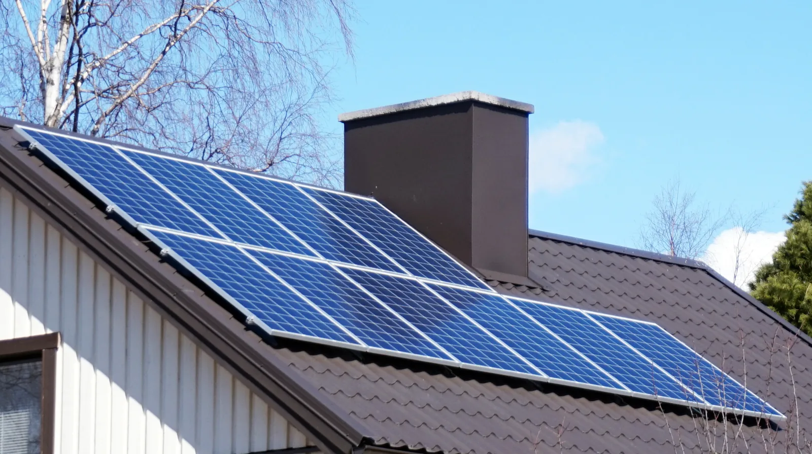
Series resistor and power of a solar cell
Sizing the series resistor
When the source, the series resistor and the LED are in series, the same current $I$ flows through all of them. By Kirchhoff's voltage law the voltage of the source is shared between the resistor and the LED, $U = U_R + U_\text{D}$ (chapter Kirchhoff's laws and potential in an electric circuit). The resistor obeys Ohm's law, $U_R = RI$, so the resistance of the series resistor is
$$R = \frac{U - U_\text{D}}{I}$$
where $R$ is the resistance of the series resistor ($\Omega$), $U$ the voltage of the source ($\text{V}$), $U_\text{D}$ the voltage of the LED or the diode ($\text{V}$) and $I$ the current ($\text{A}$). For the voltage of the LED the value given by the manufacturer is used, because it changes only a little with the current. When the resistor is known, the current is solved from the same equation: $I = \tfrac{U - U_\text{D}}{R}$.
The power of a component is its voltage times its current (chapter Electric power and the heating of a resistor): the power of the LED is $P_\text{D} = U_\text{D} I$ and the power of the resistor $P_R = U_R I$. In the resistor electrical energy becomes internal energy of the resistor, so the resistor is chosen so that it withstands this power. In the reverse direction $I = 0$, so $U_R = RI = 0$ and the voltage of the diode is the whole voltage $U$ of the source.
The power of a solar cell
The electric power given by a solar cell or panel is
$$P = U I$$
where $P$ is the power ($\text{W}$), $U$ the voltage between the terminals of the cell ($\text{V}$) and $I$ the current ($\text{A}$). In a short circuit $U = 0$ and at open circuit $I = 0$, so in both the power is zero. Between them is the maximum power point, the knee of the curve, where the power is greatest. On a $(U, I)$ graph the power is the area of the rectangle between the origin and a point of the curve.
The greatest power of the panel in the figure is about $0.92\,\text{W}$, when the voltage is about $5.0\,\text{V}$ and the current $184\,\text{mA}$. The load resistance is then $5.0\,\text{V} : 0.184\,\text{A} \approx 27\,\Omega$. The maximum power point changes with the light intensity, so the control electronics of solar power plants and chargers keep seeking it.
Efficiency
The efficiency of a cell is the electric power it gives divided by the power of the light arriving at the cell (chapter Efficiency). The power of the light is the light intensity times the area of the cell, and the electric power $P$ is the power of the cell at the maximum power point, so
$$\eta = \frac{P}{G A}$$
where $\eta$ is the efficiency, $P$ the electric power of the cell ($\text{W}$), $G$ the light intensity, that is, the radiant power per area ($\text{W/m}^2$), and $A$ the area of the cell ($\text{m}^2$). On a clear summer day, when the sun shines perpendicularly onto the cell, $G$ is about $1000\,\text{W/m}^2$. The area of the panel in the figure is $60\,\text{cm}^2 = 0.0060\,\text{m}^2$, so the light arriving at it is $1000\,\tfrac{\text{W}}{\text{m}^2} \cdot 0.0060\,\text{m}^2 = 6.0\,\text{W}$, and the efficiency is $0.92\,\text{W} : 6.0\,\text{W} \approx 15\,\%$. The efficiency of ordinary silicon cells is about $15$–$22\,\%$.
Common misconception
Many calculate the series resistor by dividing the whole voltage of the source by the current, $R = \tfrac{U}{I}$. But across the resistor there is only the part of the voltage that is not across the LED, $U - U_\text{D}$. A resistor that is too large gives too small a current, and the LED shines dimly.
Another mistake is to think that a diode is a resistor with a constant resistance. The ratio of the voltage to the current of a diode, $U_\text{D} : I$, changes strongly with the current: below the threshold voltage hardly any current flows, and above it a small increase in voltage increases the current a lot. A third mistake is to calculate the power of a solar cell as the product of the short-circuit current and the open-circuit voltage. They do not occur at the same time: in a short circuit the voltage is zero and at open circuit the current is zero.
Summary
- Semiconductors, such as silicon, conduct electricity worse than metals and better than insulators. Diodes, LEDs and solar cells are made of them.
- A diode lets current through in one direction only. In the forward direction the anode is on the side of the positive terminal of the source and current flows; in the reverse direction no current flows and the whole voltage of the source is across the diode.
- Current starts to flow when the voltage of the diode reaches the threshold voltage: about $0.6$–$0.7\,\text{V}$ for a silicon diode and about $1.8$–$3.3\,\text{V}$ for LEDs, depending on the colour. A diode does not obey Ohm's law.
- A series resistor is connected in series with an LED to limit the current: $R = \tfrac{U - U_\text{D}}{I}$.
- A solar cell is a direct-voltage source. The short-circuit current is directly proportional to the light intensity, and the open-circuit voltage changes only a little. The power $P = UI$ is greatest at the maximum power point, and the efficiency is $\eta = \tfrac{P}{GA}$.
Optional Return to your predictions
Compare your predictions with the values of the model in the experiments and with the formula $R = \tfrac{U - U_\text{D}}{I}$. Then return to the opening question: why does an LED light up only when connected one way round, and why does it need a resistor?
Would you change your prediction?
Apply
Worked example
Problem
The red LED of a bicycle's rear light is run on a $6.0\,\text{V}$ battery. The voltage of the LED is $2.0\,\text{V}$ when its current is $20\,\text{mA}$. What series resistor is needed, and how large is the power that becomes internal energy in the resistor?
Step 1/7
Given and find. The voltage of the source $U = 6.0\,\text{V}$, the voltage of the LED $U_\text{D} = 2.0\,\text{V}$ and the current $I = 20\,\text{mA}$. We are asked for the resistance $R$ of the series resistor and the power $P_R$ of the resistor.
Step 2/7
Principle. The battery, the resistor and the LED are in series, so the same current flows through all of them. The voltage of the battery is shared between the resistor and the LED, $U = U_R + U_\text{D}$, and the voltage of the resistor is $U_R = RI$. The power of the resistor is its voltage times the current.
Step 3/7
Formula solved.
$$\begin{aligned} R &= \frac{U - U_\text{D}}{I} \\ P_R &= (U - U_\text{D}) I \end{aligned}$$
Step 4/7
Conversions. The current in amperes:
Step 5/7
Substitution. $$\begin{aligned} R &= \frac{U - U_\text{D}}{I} \\ \phantom{R} &= \frac{6.0\,\text{V} - 2.0\,\text{V}}{0.020\,\text{A}} \\ \phantom{R} &= 200\,\Omega \\ P_R &= 4.0\,\text{V} \cdot 0.020\,\text{A} \\ \phantom{P_R} &= 0.080\,\text{W} \end{aligned}$$
Step 6/7
Answer. The resistance of the series resistor is $200\,\Omega$, and the power that becomes internal energy in the resistor is $0.080\,\text{W}$, two significant figures like the voltages and the current.
Step 7/7
Reasonableness. The power of the LED is $2.0\,\text{V} \cdot 0.020\,\text{A} = 0.040\,\text{W}$, and the total $0.080\,\text{W} + 0.040\,\text{W} = 0.12\,\text{W}$ is the same as the power of the battery $6.0\,\text{V} \cdot 0.020\,\text{A}$. If a shop has only $220\,\Omega$ resistors, the current is $4.0\,\text{V} : 220\,\Omega \approx 18\,\text{mA}$, slightly smaller, so the LED is not overloaded.
Find the error
Apply to a new situation
A solar panel of a cabin gives its greatest power when its voltage is $18.0\,\text{V}$ and its current $5.50\,\text{A}$. The panel is connected straight to a $12\,\text{V}$ battery without control electronics, and the battery holds the voltage of the panel at $12.8\,\text{V}$. The current of the panel is then $5.80\,\text{A}$.
How much smaller is the power of the panel when connected to the battery than at the maximum power point?
Hint 1: a guiding question
The power of the panel is its voltage times its current. Calculate the power separately at both operating points.
Hint 2: what is the connection
At the maximum power point $P_1 = 18.0\,\text{V} \cdot 5.50\,\text{A}$ and connected to the battery $P_2 = 12.8\,\text{V} \cdot 5.80\,\text{A}$.
Hint 3: an intermediate step
$P_1 = 99.0\,\text{W}$ and $P_2 = 74.24\,\text{W}$. What is asked is their difference.
Show the solution
Given
at the maximum power point $U_1 = 18.0\,\text{V}$ and $I_1 = 5.50\,\text{A}$, connected to the battery $U_2 = 12.8\,\text{V}$ and $I_2 = 5.80\,\text{A}$
Find
the decrease in power $\Delta P$ in watts
Principle
A solar panel is a direct-voltage source, and its power is the voltage times the current. The battery determines the voltage of the panel, so the panel works at a different point of its $(U, I)$ curve than the maximum power point. The current there is slightly greater, but the voltage is much smaller.
Formula
$P_1 = U_1 I_1$ and $P_2 = U_2 I_2$, from which $\Delta P = U_1 I_1 - U_2 I_2$
Conversions
None needed: the voltages are in volts and the currents in amperes, and $\text{V} \cdot \text{A} = \text{W}$.
Substitution
Answer
$24.8\,\text{W}$
Three significant figures, because the given voltages and currents have three significant figures and the precision of the difference is a tenth of a watt.
Reasonableness
Connected to the battery the panel gives about $74\,\text{W} : 99\,\text{W} \approx 75\,\%$ of its greatest power, so a quarter is lost. The current rose only about $5\,\%$, but the voltage fell about $30\,\%$. This is why solar chargers have a controller that seeks the maximum power point.
Check your understanding
Exit ticket
Answer on your own first and only then open the answer.
- What does it mean that a diode is connected in the reverse direction, and what is the voltage across the diode then?
Answer
In the reverse direction the cathode of the diode is on the side of the positive terminal of the source, and practically no current flows. Since $I = 0$, the voltage of a resistor in series is $RI = 0$, and the whole voltage of the source is across the diode.
- The short-circuit current of a solar panel is $5.0\,\text{A}$ and the open-circuit voltage $21\,\text{V}$. Why can the power of the panel not be $5.0\,\text{A} \cdot 21\,\text{V} = 105\,\text{W}$?
Answer
The greatest current and the greatest voltage do not occur at the same time: in a short circuit the voltage is zero and at open circuit the current is zero, so the power is zero in both. The greatest power is obtained at the maximum power point, where both the voltage and the current are slightly smaller than their greatest values, so the power stays below $105\,\text{W}$.
1. Concept
2. Graph
Optional 3. Explain the series resistor
A friend connects a red LED straight to a $4.5\,\text{V}$ battery, because “even a light bulb does not need a resistor”. The LED flashes and goes out for good. Explain what happened and why a light bulb withstands the same connection.
Model answer
The voltage of the LED in the forward direction is about $2\,\text{V}$, and above that a small increase in voltage increases the current very much. Without a series resistor almost the whole voltage of the battery was across the LED, and only the internal resistance of the battery and the wires limited the current. If their resistance is about $1\,\Omega$, the current is of the order of $(4.5\,\text{V} - 2.0\,\text{V}) : 1\,\Omega \approx 2.5\,\text{A}$, over a hundred times the recommended $20\,\text{mA}$ of the LED. The LED overheated and broke. The filament of a light bulb obeys Ohm's law approximately, and its resistance grows as the filament heats up, so the bulb limits its own current. With an LED a series resistor is therefore needed, which takes the extra voltage and determines the current.
Assess your own answer
Tick the points your own answer already contains.
Review the theory summary and practise with the exercises.
Exercises
Level 1 · basic practice 5 exercises
One formula or one step of reasoning. Core exercises first, the rest is extra practice.
- Exercise 14-1Core
The voltage of a red LED is $2.0\,\text{V}$, and a current of $15\,\text{mA}$ flows through it. What is the power of the LED? Give the answer in milliwatts.
Answer
$30\,\text{mW}$
Show the solution
Given
voltage of the LED $U_\text{D} = 2.0\,\text{V}$, current $I = 15\,\text{mA}$
Find
the power $P_\text{D}$ of the LED in milliwatts
Principle
The electric power of a component is its voltage times the current flowing through it. This holds also for an LED, although it does not obey Ohm's law, because power is always the energy that the charge gives up in the component per unit time.
Formula
$P_\text{D} = U_\text{D} I$
Conversions
$I$$= 15\,\text{mA}$$= 15 \cdot 10^{-3}\,\text{A}$$= 0.015\,\text{A}$Substitution
$P_\text{D}$$= 2.0\,\text{V} \cdot 0.015\,\text{A}$$= 0.030\,\text{W}$$= 30\,\text{mW}$Answer
$30\,\text{mW}$
Two significant figures like the voltage and the current.
Reasonableness
The unit is consistent: $\text{V} \cdot \text{mA} = \text{mW}$, and $2 \cdot 15 = 30$. The power of an indicator LED is tens of milliwatts, much smaller than that of a light bulb, as we know from experience.
- Exercise 14-2Core
A white LED is connected to a $5.0\,\text{V}$ USB power supply through a series resistor. The voltage of the LED is $3.1\,\text{V}$, and the desired current is $20\,\text{mA}$.
What series resistor is needed? Give the answer in ohms.
Answer
$95\,\Omega$
Show the solution
Given
voltage of the source $U = 5.0\,\text{V}$, voltage of the LED $U_\text{D} = 3.1\,\text{V}$, current $I = 20\,\text{mA}$
Find
the resistance $R$ of the series resistor in ohms
Principle
The source, the resistor and the LED are in series, so the same current flows through all of them. By Kirchhoff's voltage law the voltage of the source is shared: $U = U_R + U_\text{D}$. The resistor obeys Ohm's law, $U_R = RI$.
Formula
$U = RI + U_\text{D}$, from which $R = \dfrac{U - U_\text{D}}{I}$
Conversions
$I$$= 20\,\text{mA}$$= 20 \cdot 10^{-3}\,\text{A}$$= 0.020\,\text{A}$Substitution
$R$$= \dfrac{5.0\,\text{V} - 3.1\,\text{V}}{0.020\,\text{A}}$$= \dfrac{1.9\,\text{V}}{0.020\,\text{A}}$$= 95\,\Omega$Answer
$95\,\Omega$
Two significant figures like the difference of the voltages $1.9\,\text{V}$ and the current.
Reasonableness
Check: $95\,\Omega \cdot 0.020\,\text{A} = 1.9\,\text{V}$, and $1.9\,\text{V} + 3.1\,\text{V} = 5.0\,\text{V}$. The voltage of a white LED is large, so only a little voltage is left for the resistor and the resistor is small.
- Exercise 14-3
A silicon diode is connected in the forward direction to a $9.0\,\text{V}$ battery through a $1.0\,\text{k}\Omega$ resistor. The voltage of the diode is $0.70\,\text{V}$.
What current flows in the circuit? Give the answer in milliamperes.
Answer
$8.3\,\text{mA}$
Show the solution
Given
voltage of the battery $U = 9.0\,\text{V}$, resistor $R = 1.0\,\text{k}\Omega$, voltage of the diode $U_\text{D} = 0.70\,\text{V}$, diode in the forward direction
Find
the current $I$ in milliamperes
Principle
The diode is in the forward direction, so current flows, and the voltage of the diode is the $0.70\,\text{V}$ given in the task. The battery, the resistor and the diode are in series: the voltage of the battery is shared between the resistor and the diode, and the voltage of the resistor is $U_R = RI$.
Formula
$U = RI + U_\text{D}$, from which $I = \dfrac{U - U_\text{D}}{R}$
Conversions
$R$$= 1.0\,\text{k}\Omega$$= 1.0 \cdot 1000\,\Omega$$= 1000\,\Omega$Substitution
$I$$= \dfrac{9.0\,\text{V} - 0.70\,\text{V}}{1000\,\Omega}$$= \dfrac{8.3\,\text{V}}{1000\,\Omega}$$= 0.0083\,\text{A}$$= 8.3\,\text{mA}$Answer
$8.3\,\text{mA}$
Two significant figures like the voltage $9.0\,\text{V}$ and the resistance $1.0\,\text{k}\Omega$.
Reasonableness
Without the diode the current would be $9.0\,\text{V} : 1000\,\Omega = 9.0\,\text{mA}$. The diode takes only a little voltage, so the current is slightly smaller, as it should be.
- Exercise 14-4
The solar panel of a cabin charges a battery. The voltage of the panel is $17.5\,\text{V}$, and the current it gives is $5.40\,\text{A}$.
What is the power of the panel?
Answer
$94.5\,\text{W}$
Show the solution
Given
voltage of the panel $U = 17.5\,\text{V}$, current $I = 5.40\,\text{A}$
Find
the power $P$ of the panel in watts
Principle
A solar panel is a direct-voltage source. The electric power it gives is the voltage between its terminals times the current, like the power of any source.
Formula
$P = UI$
Conversions
None needed: the voltage is in volts and the current in amperes, and $\text{V} \cdot \text{A} = \text{W}$.
Substitution
$P$$= 17.5\,\text{V} \cdot 5.40\,\text{A}$$= 94.5\,\text{W}$Answer
$94.5\,\text{W}$
Three significant figures like the voltage and the current.
Reasonableness
The estimate $18\,\text{V} \cdot 5\,\text{A} = 90\,\text{W}$ is close to the result. A panel of about $100\,\text{W}$ is an ordinary solar panel for a cabin.
- Exercise 14-5
The graph shows the characteristic curve of a green LED. Read from the graph the voltage of the LED when its current is $10\,\text{mA}$, and calculate the power of the LED at this current. Give the answer in milliwatts.
Answer
$22\,\text{mW}$
Show the solution
Given
the characteristic curve of a green LED, current $I = 10\,\text{mA}$
Find
the power $P_\text{D}$ of the LED in milliwatts
Principle
The characteristic curve tells what voltage is across the LED at each current. The power is the voltage times the current, so we need the voltage that corresponds to the current $10\,\text{mA}$.
Reading the graph
From $10\,\text{mA}$ on the vertical axis we go horizontally to the curve. The curve meets the $10\,\text{mA}$ grid line at a vertical grid line that is one $0.2\,\text{V}$ square to the right of $2.0\,\text{V}$, so $U_\text{D} = 2.2\,\text{V}$.
Formula
$P_\text{D} = U_\text{D} I$
Conversions
$I = 10\,\text{mA} = 0.010\,\text{A}$
Substitution
$P_\text{D}$$= 2.2\,\text{V} \cdot 0.010\,\text{A}$$= 0.022\,\text{W}$$= 22\,\text{mW}$Answer
$22\,\text{mW}$
Two significant figures, because the voltage is read from a $0.2\,\text{V}$ grid and the current from a $5\,\text{mA}$ grid.
Reasonableness
The voltage of the green LED, $2.2\,\text{V}$, lies between that of the red ($1.8$–$2.0\,\text{V}$) and the blue (about $3\,\text{V}$), as in the text of the chapter. The power is a few tens of milliwatts, ordinary for an indicator light.
Level 2 · applied practice 4 exercises
Two steps, working with measured data, a unit conversion or rearranging a formula. Core exercises first, the rest is extra practice.
- Exercise 14-6Core
A student connects a red LED and a $470\,\Omega$ series resistor in series to a $9.0\,\text{V}$ battery, but the LED is accidentally in the reverse direction. Assume that no current flows through the LED in the reverse direction.
What is the voltage across the LED? Give the answer in volts.
Answer
$9.0\,\text{V}$
Show the solution
Given
voltage of the battery $U = 9.0\,\text{V}$, series resistor $R = 470\,\Omega$, LED in the reverse direction; assumption: no current flows in the reverse direction
Find
the voltage $U_\text{D}$ of the LED in volts
Principle
In the reverse direction practically no current flows through the diode. Since the LED and the resistor are in series, the current of the resistor is also zero, so by Ohm's law the voltage of the resistor is zero. By Kirchhoff's voltage law the whole voltage of the battery is then across the LED.
Formula
$U = U_R + U_\text{D}$ and $U_R = RI$, so with the current $I = 0$ we get $U_\text{D} = U - RI = U$
Conversions
None needed: the current is zero, so the value of the resistor does not need converting.
Substitution
$U_\text{D}$$= 9.0\,\text{V} - 470\,\Omega \cdot 0\,\text{A}$$= 9.0\,\text{V}$Answer
$9.0\,\text{V}$
Two significant figures like the voltage of the battery.
Reasonableness
The series resistor does not protect an LED in the reverse direction, because there is no voltage across the resistor. An ordinary LED often withstands only about $5\,\text{V}$ in the reverse direction, so $9.0\,\text{V}$ can break it; this is why the polarity is checked before connecting.
- Exercise 14-7Core
Two red LEDs and a series resistor are connected in series to a $9.0\,\text{V}$ battery. The voltage of each LED is $2.0\,\text{V}$, and the desired current is $20\,\text{mA}$.
What series resistor is needed? Give the answer in ohms.
Answer
$250\,\Omega$
Show the solution
Given
voltage of the battery $U = 9.0\,\text{V}$, two LEDs in series, the voltage of each $U_\text{D} = 2.0\,\text{V}$, current $I = 20\,\text{mA}$
Find
the resistance $R$ of the series resistor in ohms
Principle
All the components are in series, so the same current flows through them. The voltage of the battery is shared between the resistor and both LEDs: $U = U_R + 2U_\text{D}$. The voltage of the resistor is $U_R = RI$.
Formula
$U = RI + 2U_\text{D}$, from which $R = \dfrac{U - 2U_\text{D}}{I}$
Conversions
$I = 20\,\text{mA} = 0.020\,\text{A}$
Substitution
$R$$= \dfrac{9.0\,\text{V} - 2 \cdot 2.0\,\text{V}}{0.020\,\text{A}}$$= \dfrac{5.0\,\text{V}}{0.020\,\text{A}}$$= 250\,\Omega$Answer
$250\,\Omega$
Two significant figures like the voltages and the current.
Reasonableness
For one LED the resistor would be $7.0\,\text{V} : 0.020\,\text{A} = 350\,\Omega$. The second LED takes $2.0\,\text{V}$ more, so less voltage is left for the resistor and the resistor is smaller.
- Exercise 14-8
The area of a solar panel on the roof of a detached house is $1.6\,\text{m}^2$. When the light intensity is $800\,\text{W/m}^2$, the panel gives an electric power of $260\,\text{W}$.
What is the efficiency of the panel? Give the answer as a percentage.
Answer
$20\,\%$
Show the solution
Given
area $A = 1.6\,\text{m}^2$, light intensity $G = 800\,\text{W/m}^2$, electric power $P = 260\,\text{W}$
Find
the efficiency $\eta$ as a percentage
Principle
Efficiency is the useful power divided by the power taken in. The panel receives the power of the light, which is the light intensity times the area, and the useful power is the electric power given by the panel.
Formula
$\eta = \dfrac{P}{GA}$
Conversions
None needed: $\tfrac{\text{W}}{\text{m}^2} \cdot \text{m}^2 = \text{W}$. Finally the ratio is changed to a percentage by multiplying by a hundred.
Substitution
$\eta$$= \dfrac{260\,\text{W}}{800\,\tfrac{\text{W}}{\text{m}^2} \cdot 1.6\,\text{m}^2}$$= \dfrac{260\,\text{W}}{1280\,\text{W}}$$= 0.203$$= 20.3\,\%$Answer
$20\,\%$
Two significant figures like the area $1.6\,\text{m}^2$.
Reasonableness
About $1300\,\text{W}$ of light arrives at the panel, and about a fifth of it becomes electricity. The efficiency is in the range of ordinary silicon cells, $15$–$22\,\%$.
- Exercise 14-9
The solar cell of a garden lamp charges the battery of the lamp during the day. The average power of the cell is $0.35\,\text{W}$, and it charges the battery for $6.0\,\text{h}$.
How much electrical energy does the cell produce during this time? Give the answer in kilojoules.
Answer
$7.6\,\text{kJ}$
Show the solution
Given
power of the cell $P = 0.35\,\text{W}$, time $t = 6.0\,\text{h}$
Find
the electrical energy $E$ in kilojoules
Principle
Power is energy per unit time. When the power is assumed to be the average power all the time, the energy is the power times the time.
Formula
$P = \dfrac{E}{t}$, from which $E = Pt$
Conversions
$t$$= 6.0\,\text{h}$$= 6.0 \cdot 3600\,\text{s}$$= 21\,600\,\text{s}$Substitution
$E$$= 0.35\,\text{W} \cdot 21\,600\,\text{s}$$= 7560\,\text{J}$$= 7.56\,\text{kJ}$Answer
$7.6\,\text{kJ}$
Two significant figures like the power and the time.
Reasonableness
In watt-hours the energy is $0.35\,\text{W} \cdot 6.0\,\text{h} = 2.1\,\text{Wh}$, and $2.1 \cdot 3600\,\text{J} = 7560\,\text{J}$, the same result. The amount is of the order of a small battery, which is enough for one LED for the whole night.
Level 3 · challenging 3 exercises
Optional: application, two ideas together or a new situation where you reason for yourself.
- Exercise 14-10
A flashlight has a red LED with a voltage of $2.0\,\text{V}$ and a $120\,\Omega$ series resistor. The voltage of new batteries is $4.5\,\text{V}$, and in use it falls to $3.6\,\text{V}$. Assume that the voltage of the LED stays the same.
By what percentage does the current of the LED decrease when the voltage of the batteries falls like this? Give the answer as a percentage.
Answer
$36\,\%$
Show the solution
Given
voltage of the LED $U_\text{D} = 2.0\,\text{V}$, series resistor $R = 120\,\Omega$, voltage of the batteries first $U_1 = 4.5\,\text{V}$ and finally $U_2 = 3.6\,\text{V}$
Find
the decrease of the current as a percentage of the original current
Principle
By assumption the voltage of the LED stays the same, so the whole change in voltage falls on the resistor. The current is obtained from Kirchhoff's voltage law and Ohm's law. The voltage of the resistor decreases proportionally more than the voltage of the batteries, because the constant voltage of the LED has been subtracted from it.
Formula
$I = \dfrac{U - U_\text{D}}{R}$, so $I_1 = \dfrac{U_1 - U_\text{D}}{R}$, $I_2 = \dfrac{U_2 - U_\text{D}}{R}$ and the relative change is $\dfrac{I_1 - I_2}{I_1}$
Conversions
None needed: the currents are divided by each other, so the unit cancels. The ratio is changed to a percentage by multiplying by a hundred.
Substitution
$I_1$$= \dfrac{4.5\,\text{V} - 2.0\,\text{V}}{120\,\Omega}$$= 0.02083\,\text{A}$$I_2$$= \dfrac{3.6\,\text{V} - 2.0\,\text{V}}{120\,\Omega}$$= 0.01333\,\text{A}$$\dfrac{I_1 - I_2}{I_1}$$= \dfrac{0.00750\,\text{A}}{0.02083\,\text{A}}$$= 0.36$Answer
$36\,\%$
Two significant figures like the voltages.
Reasonableness
The voltage of the batteries fell by only $0.9\,\text{V} : 4.5\,\text{V} = 20\,\%$, but the voltage of the resistor fell from $2.5\,\text{V}$ to $1.6\,\text{V}$, that is, by $36\,\%$. This is why an LED flashlight clearly dims when the batteries start to run down.
- Exercise 14-11
The voltage and the current of a solar panel were measured with different load resistances in the same lighting. The measured pairs $(U;\ I)$ were: $(0\,\text{V};\ 3.30\,\text{A})$, $(10.0\,\text{V};\ 3.25\,\text{A})$, $(14.0\,\text{V};\ 3.18\,\text{A})$, $(16.0\,\text{V};\ 3.05\,\text{A})$, $(17.0\,\text{V};\ 2.90\,\text{A})$, $(18.0\,\text{V};\ 2.55\,\text{A})$, $(19.0\,\text{V};\ 1.90\,\text{A})$, $(20.0\,\text{V};\ 0.95\,\text{A})$, $(21.0\,\text{V};\ 0\,\text{A})$.
With which load resistance does the panel give the greatest power of the measurements? Give the answer in ohms.
Answer
$5.9\,\Omega$
Show the solution
Given
measured pairs $(U$; $I)$ of the panel in the same lighting (nine pairs in the task)
Find
the load resistance $R$ in ohms when the power is the greatest of the measurements
Principle
The power of the panel is $P = UI$. It is zero in a short circuit and at open circuit, so the greatest power is between them, at the maximum power point. We calculate the power of each measurement and choose the greatest, and the load resistance is obtained from Ohm's law $U = RI$ for the load, because the voltage of the load is the voltage of the panel and its current is the current of the panel.
Formula
$P = UI$, and at the maximum power point $U = RI$, from which $R = \dfrac{U}{I}$
Conversions
None needed: the voltages are in volts and the currents in amperes.
Substitution
The powers are $0\,\text{W}$, $32.5\,\text{W}$, $44.5\,\text{W}$, $48.8\,\text{W}$, $49.3\,\text{W}$, $45.9\,\text{W}$, $36.1\,\text{W}$, $19.0\,\text{W}$ and $0\,\text{W}$. The greatest is $17.0\,\text{V} \cdot 2.90\,\text{A} = 49.3\,\text{W}$, so
$R$$= \dfrac{17.0\,\text{V}}{2.90\,\text{A}}$$= 5.86\,\Omega$Answer
$5.9\,\Omega$
Two significant figures, because the greatest power and the neighbouring $48.8\,\text{W}$ are so close to each other that the true maximum power point may lie between the measurements.
Reasonableness
In a short circuit the load resistance is zero and at open circuit very large, and $5.9\,\Omega$ lies between them. The greatest power is at the knee of the curve, where the current has already begun to fall but the voltage is almost at its greatest.
- Exercise 14-12
An LED strip has many identical groups in parallel, and each group has three white LEDs in series and a series resistor. The strip is connected to a voltage of $12\,\text{V}$. The voltage of each LED is $3.0\,\text{V}$, and the current of each group is $20\,\text{mA}$.
What percentage of the electric power of the strip becomes internal energy of the series resistors?
Answer
$25\,\%$
Show the solution
Given
voltage of the strip $U = 12\,\text{V}$, three LEDs in series in a group, the voltage of each $U_\text{D} = 3.0\,\text{V}$, current of the group $I = 20\,\text{mA}$
Find
the share of the power of the strip that goes to the series resistors, as a percentage
Principle
The groups are in parallel, so across each group there is $12\,\text{V}$, and the groups are identical, so it is enough to consider one group. In a group the LEDs and the resistor are in series, so the same current flows through all of them, and the voltage is shared: $U = U_R + 3U_\text{D}$. The power of the resistor is $U_R I$ and the power of the whole group $UI$.
Formula
$U_R = U - 3U_\text{D}$ and the share is $\dfrac{U_R I}{UI}$, so the share is $\dfrac{U - 3U_\text{D}}{U}$
Conversions
None needed: the current cancels, and the ratio of the voltages is a ratio. Finally we multiply by a hundred.
Substitution
$\dfrac{12\,\text{V} - 3 \cdot 3.0\,\text{V}}{12\,\text{V}}$$= \dfrac{3.0\,\text{V}}{12\,\text{V}}$$= 0.25$$= 25\,\%$Answer
$25\,\%$
Two significant figures like the voltage of the LED $3.0\,\text{V}$.
Reasonableness
The power of one group is $12\,\text{V} \cdot 0.020\,\text{A} = 0.24\,\text{W}$, and that of the resistor $3.0\,\text{V} \cdot 0.020\,\text{A} = 0.060\,\text{W}$, which is a quarter. This is why the strip has three LEDs in series: with one LED $9.0\,\text{V} : 12\,\text{V} = 75\,\%$ of the power would become internal energy in the resistor.
Photographs
- Jyväskylä - solar panels. Tiia Monto. source, CC BY-SA 4.0
