
The capacitor and its energy
Why does the flash of a camera need a few seconds of charging time, although the flash itself lasts only a millisecond?
Prior knowledge
- The strength of a uniform electric field between plates is $E = \tfrac{U}{d}$chapter Uniform electric field
- When a charge $Q$ moves across a voltage $U$, its energy changes by $QU$chapter Potential energy and potential in an electric field
- Electric current is the movement of charge, and power is energy per unit of timechapter Electric power and heating of a resistor
Core path: follow the steps in order. Tasks marked Optional give extra practice. Optional tasks: 4.
Think about it
A camera has two ordinary AA batteries. After a flash picture has been taken, the camera shows for a few seconds that the flash is charging. The flash itself lasts about a millisecond, and it is so bright that it lights up the whole room. The batteries could not deliver that much power directly.
Where is the energy for the flash collected, and why does collecting it take seconds but releasing it only a millisecond?
Optional Review: the field between plates
Predict
Make your predictions before investigating 2 questions
Prediction 1: the voltage doubles
Prediction 2: a dielectric in a disconnected capacitor
Investigate
Change the distance and the area of the plates, the voltage of the source and the dielectric. Disconnect the source and see what stays the same.
Simulation
How to use
Set the distance of the plates $d$, the area of the plate $A$ and the voltage of the source $U_0$ with the sliders, and the dielectric and the source from the menus. When the source is connected, the voltage of the capacitor is the voltage of the source. When you choose disconnected, the switch opens and the charge of the plates stays the same as it was at the moment of disconnecting; the slider for the voltage of the source then has no effect. The red circles are positive and the blue ones negative charges, and their number describes the charge per area. The density of the green field lines describes the strength of the field. The straight line of the graph is $U = \tfrac{Q}{C}$, and the area of the orange triangle is the energy. A spark between the plates means a dielectric breakdown.
Assumptions of the model
The plates are parallel, and the distance between them is small compared with the size of the plates, so the field is uniform and the effect of the edges is ignored. The dielectric fills the space between the plates completely. The relative permittivities and the dielectric strengths of the dielectrics are rounded table values: air $1.0$ and $3\,\text{MV/m}$, Teflon $2.1$ and $60\,\text{MV/m}$, paper $3.7$ and $16\,\text{MV/m}$, glass $5.6$ and $14\,\text{MV/m}$. Charging and discharging happen immediately in the model, so the picture always shows the final state. A disconnected capacitor does not leak, but in a breakdown it discharges. The numbers are values calculated by the model, not measurements.
How the calculation works
The capacitance is calculated from the formula of a parallel-plate capacitor
$$C = \frac{\varepsilon_0 \varepsilon_\text{r} A}{d}$$
where $\varepsilon_0 = 8.854 \cdot 10^{-12}\,\text{F/m}$. When the source is connected, $U = U_0$ and $Q = C U_0$. At the moment of disconnecting, the charge is kept, and after that the voltage is $U = \tfrac{Q}{C}$. The field is $E = \tfrac{U}{d}$, and the energy is $W = \tfrac{1}{2} Q U$. A breakdown happens when $E$ exceeds the dielectric strength $E_\text{max}$ of the dielectric. The units fit together: $\text{pF} \cdot \text{kV} = \text{nC}$, $\text{nC} \cdot \text{kV} = \mu\text{J}$ and $\text{kV} : \text{mm} = \text{MV/m}$.
Experiment 1: charge and energy as a function of voltage
Test prediction 1. The source is connected, and the distance of the plates, the area and the dielectric stay constant; change only the voltage of the source. Record the charge and the energy at at least three voltages, for example $0.5$, $1.0$, $1.5$ and $2.0\,\text{kV}$. Also calculate $Q : U$ for each row. What do you notice?
Initial state: area of the plate = $200\,\text{cm}^2$, distance of the plates = $2\,\text{mm}$, dielectric: air, source: connected, voltage of the source = $0{.}5\,\text{kV}$. Kept constant: area of the plate, distance of the plates, dielectric, source. Varied: voltage of the source.
| voltage of the source | $Q$ $(\text{nC})$ | $W$ $(\mu\text{J})$ |
|---|
Experiment 2: the distance of the plates
The source is connected, and its voltage is $1.0\,\text{kV}$. The area and the dielectric stay constant; change only the distance of the plates. Record the capacitance, the charge and the strength of the field at at least three distances, for example $1.0$, $2.0$, $4.0$ and $8.0\,\text{mm}$. How does the capacitance depend on the distance?
Initial state: area of the plate = $200\,\text{cm}^2$, dielectric: air, source: connected, voltage of the source = $1\,\text{kV}$, distance of the plates = $1\,\text{mm}$. Kept constant: area of the plate, dielectric, source, voltage of the source. Varied: distance of the plates.
| distance of the plates | $C$ $(\text{pF})$ | $Q$ $(\text{nC})$ | $E$ $(\text{MV/m})$ |
|---|
Experiment 3: a dielectric in a disconnected capacitor
Test prediction 2. The capacitor is charged to $1.0\,\text{kV}$ with air between the plates, and the source is disconnected. The distance and the area stay constant; change only the dielectric. Record the charge, the voltage and the energy with at least two dielectrics. What stays the same, and what changes?
Initial state: area of the plate = $200\,\text{cm}^2$, distance of the plates = $2\,\text{mm}$, voltage of the source = $1\,\text{kV}$, dielectric: air, source: disconnected. Kept constant: area of the plate, distance of the plates, voltage of the source, source. Varied: dielectric.
| dielectric | $Q$ $(\text{nC})$ | $U$ $(\text{kV})$ | $W$ $(\mu\text{J})$ |
|---|
Optional Experiment 4: a dielectric when the source is connected
Repeat experiment 3 so that the source stays connected at a voltage of $1.0\,\text{kV}$. Change only the dielectric, and record the charge, the voltage and the energy. Compare the results with experiment 3: what stays the same now?
Initial state: area of the plate = $200\,\text{cm}^2$, distance of the plates = $2\,\text{mm}$, voltage of the source = $1\,\text{kV}$, dielectric: air, source: connected. Kept constant: area of the plate, distance of the plates, voltage of the source, source. Varied: dielectric.
| dielectric | $Q$ $(\text{nC})$ | $U$ $(\text{kV})$ | $W$ $(\mu\text{J})$ |
|---|
Experiment 5: breakdown in air
There is air between the plates over a distance of $1.0\,\text{mm}$, and the source is connected. Raise the voltage of the source gradually and record the strength of the field. At what voltage does the breakdown happen, and what is the strength of the field then?
Initial state: area of the plate = $200\,\text{cm}^2$, distance of the plates = $1\,\text{mm}$, dielectric: air, source: connected, voltage of the source = $2\,\text{kV}$. Kept constant: area of the plate, distance of the plates, dielectric, source. Varied: voltage of the source.
| voltage of the source | $E$ $(\text{MV/m})$ | breakdown (1 = yes) |
|---|
Conclusion: what determines the charge and the energy?
Write on the basis of your tables: how did the charge and the energy depend on the voltage, and how did the capacitance depend on the distance of the plates? What happened to the charge, the voltage and the energy when a dielectric was added to a disconnected capacitor?
Model answer
In experiment 1 the charge grew in the same proportion as the voltage: $Q : U$ was about $88.5\,\text{nC/kV}$ in every row, that is, the capacitance was $88.5\,\text{pF}$. The energy grew with the square of the voltage: a doubled voltage gave four times the energy, because $W = \tfrac{1}{2} Q U$ and both $Q$ and $U$ doubled. In experiment 2 the capacitance halved when the distance doubled, so the capacitance is inversely proportional to the distance. In experiment 3 the charge stayed at $88.5\,\text{nC}$, because the charge of a disconnected capacitor cannot change. The dielectric increased the capacitance, so the voltage and the energy decreased: with glass the voltage was about $0.18\,\text{kV}$ and the energy about $7.9\,\mu\text{J}$. The values are calculated by the model.
Assess your own answer
Tick the points your own answer already contains.
Review the theory summary and practise with the exercises.
Theory summary
Key idea
Two conducting plates with an insulator between them
A capacitor is two conducting bodies, for example metal plates, with an insulator (a dielectric) between them. When a capacitor is connected to a voltage source, the source moves electrons along the wires from one plate to the other. Electrons leave the plate connected to the positive terminal of the source, so it becomes positively charged, and the same number of extra electrons arrives at the plate connected to the negative terminal. The charges of the plates are therefore $+Q$ and $-Q$, and the capacitor as a whole is electrically neutral. By the charge of a capacitor $Q$ we mean the magnitude of the charge of one plate. The charges do not pass through the insulator from one plate to the other.
Between the charged plates there is a uniform electric field that points from the positive plate to the negative one. Its strength is $E = \tfrac{U}{d}$, where $U$ is the voltage between the plates and $d$ the distance of the plates (chapter Uniform electric field).
Charging and discharging
When a capacitor is charged through a resistor, at the start of charging the plates are uncharged and the voltage $U_C$ of the capacitor is zero. The whole voltage of the source is then across the resistor, and the current is at its greatest. As charge builds up on the plates, the voltage of the capacitor grows, the voltage of the resistor decreases and the current decreases. Charging ends when the voltage of the capacitor equals the voltage $U_0$ of the source: then no more current passes.
When a charged capacitor is connected, for example, to a lamp, it acts as a voltage source and discharges. The current is greatest right at the start and passes in the opposite direction to that in charging. As the charge decreases, the voltage and the current gradually decrease to zero. The greater the resistance in the circuit, the more slowly the charging and the discharging happen.
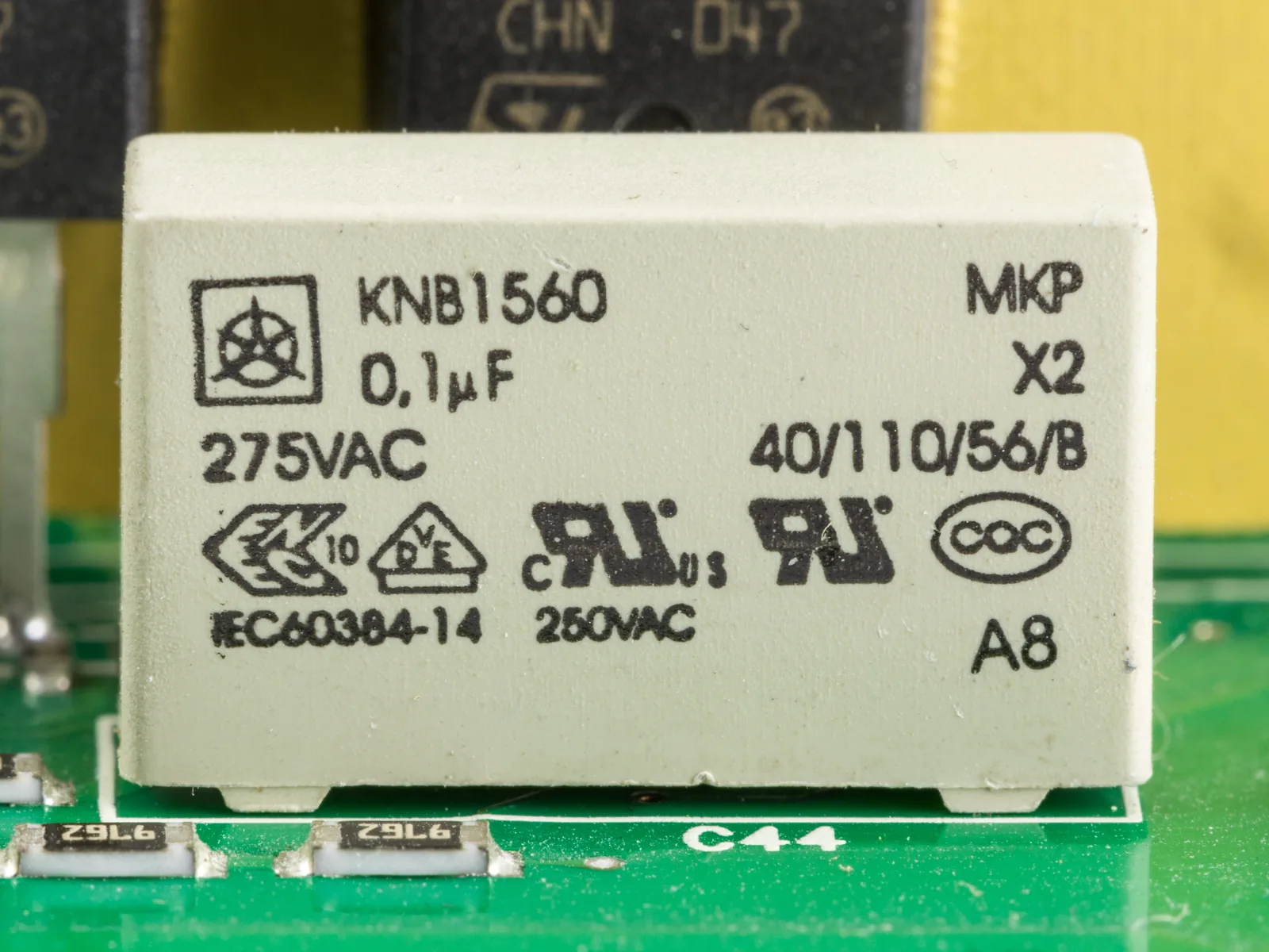
Capacitance tells how much charge a voltage brings
When the voltage of a capacitor doubles, the field between the plates doubles, and twice the charge is needed for it. The charge is thus directly proportional to the voltage. Their ratio is the capacitance of the capacitor, which depends only on the structure of the capacitor: the area $A$ of the plates, their distance $d$ and the dielectric. Larger plates have room for more charge at the same field. When the plates are closer to each other, the same voltage produces a stronger field $E = \tfrac{U}{d}$, and a stronger field requires more charge on the plates. Capacitance does not depend on the voltage or on the charge.
A dielectric increases the capacitance
In an insulator the charges cannot move freely, but the electric field shifts the electrons of the molecules slightly towards the positive plate. The dielectric becomes polarised: negative charge appears on its surface facing the positive plate and positive charge on the opposite surface. These charges weaken the field of the plates. When the plates have the same charge, the field inside the dielectric is weaker than in air, so the voltage is also smaller. The capacitance is then greater.
The energy is in the electric field
Moving charge from one plate to the other requires work, because the positive plate attracts electrons and the negative plate repels them. This work is stored as energy in the electric field between the plates, and when it discharges, the capacitor gives the energy back. The batteries of a flash unit can deliver only a small power, so charging the capacitor takes seconds. The capacitor discharges through the flash tube in a millisecond, and the same energy is released at a power thousands of times greater.
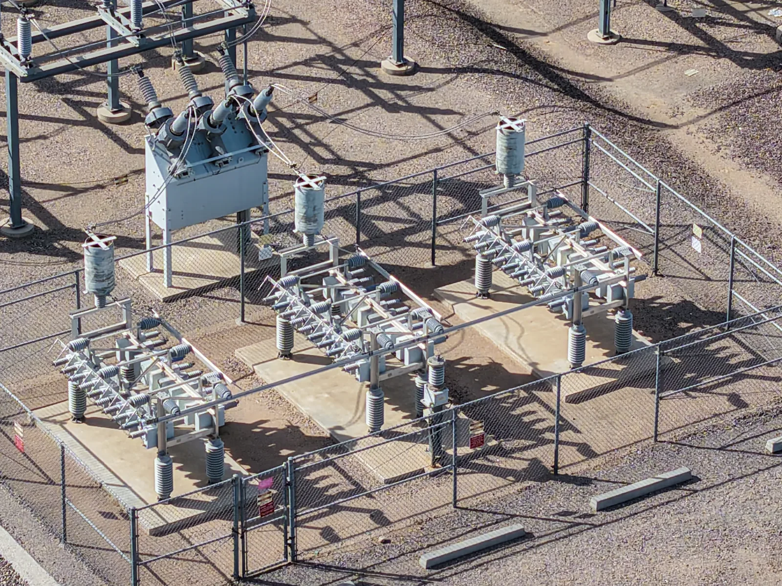
Dielectric strength
Every insulator withstands only an electric field of a certain size. When the field exceeds the dielectric strength $E_\text{max}$ of the insulator, electrons are torn from the molecules of the insulator, the insulator starts to conduct and a spark discharges between the plates. The capacitor may then be permanently damaged. That is why the greatest allowed voltage is marked on every capacitor. The dielectric strength of air is about $3\,\text{MV/m}$, and lightning is a dielectric breakdown of air on a large scale.
A large capacitor can keep a dangerous voltage for a long time after the device has been disconnected from the mains. For example, the capacitors of a microwave oven and of a flash unit can give an electric shock, so an opened device is not touched until the capacitors have been discharged.
Capacitance and the energy of a capacitor
The capacitance of a capacitor is the ratio of the charge to the voltage:
$$C = \frac{Q}{U}$$
where $C$ is the capacitance ($\text{F}$), $Q$ the charge of the capacitor ($\text{C}$) and $U$ the voltage between the plates ($\text{V}$).
The unit of capacitance is the farad, $1\,\text{F} = 1\,\tfrac{\text{C}}{\text{V}}$. The farad is a large unit, so the capacitances of ordinary capacitors are given in micro-, nano- or picofarads, for example $470\,\mu\text{F} = 470 \cdot 10^{-6}\,\text{F}$.
The parallel-plate capacitor
The capacitance of a parallel-plate capacitor is
$$C = \frac{\varepsilon_0 \varepsilon_\text{r} A}{d}$$
where $A$ is the area of a plate ($\text{m}^2$), $d$ the distance of the plates ($\text{m}$), $\varepsilon_0 = 8.854 \cdot 10^{-12}\,\text{F/m}$ the electric constant, that is, the permittivity of vacuum, and $\varepsilon_\text{r}$ the relative permittivity of the dielectric. The formula holds when the distance of the plates is small compared with the size of the plates (the field is uniform and the edges are ignored) and the dielectric fills the space between the plates. The relative permittivity tells how many times the dielectric multiplies the capacitance compared with vacuum. For air $\varepsilon_\text{r} \approx 1.0$.
| Dielectric | $\varepsilon_\text{r}$ | $E_\text{max}\ (\text{MV/m})$ |
|---|---|---|
| air | $1.0$ | $3$ |
| Teflon | $2.1$ | $60$ |
| paper | $3.7$ | $16$ |
| glass | $5.6$ | $14$ |
The values in the table are approximate: they depend on the quality, humidity and temperature of the material.
The greatest allowed voltage
The field between the plates is $E = \tfrac{U}{d}$, so the dielectric withstands the voltage
$$U_\text{max} = E_\text{max} d$$
where $U_\text{max}$ is the greatest voltage ($\text{V}$) at which no breakdown happens, $E_\text{max}$ the dielectric strength of the dielectric ($\text{V/m}$) and $d$ the thickness of the dielectric layer ($\text{m}$). For example, a layer of paper $0.010\,\text{mm}$ thick withstands about $16 \cdot 10^{6}\,\tfrac{\text{V}}{\text{m}} \cdot 0.010 \cdot 10^{-3}\,\text{m} = 160\,\text{V}$.
The energy of a capacitor
In charging, the charge grows from zero to $Q$, and the voltage grows in the same proportion from zero to $U$. When a small charge is moved from one plate to the other across a voltage, it gains an energy equal to the charge times the voltage at that moment (chapter Potential energy and potential in an electric field). The first charges move across a small voltage and the last across the whole voltage $U$, so the average voltage is $\tfrac{U}{2}$. The energy is the area of the triangle under the $(Q, U)$ graph.
The energy stored in a capacitor is
$$W = \tfrac{1}{2} Q U = \tfrac{1}{2} C U^2$$
where $W$ is the energy ($\text{J}$), $Q$ the charge ($\text{C}$), $U$ the voltage ($\text{V}$) and $C$ the capacitance ($\text{F}$). The latter form is obtained by substituting $Q = CU$. Energy is denoted by $W$, because in this chapter $E$ means the strength of the electric field. In the chapter Batteries and the charging circuit too the energy was $W$, because there $E$ was the source voltage.
The source moves the whole charge $Q$ across its full voltage $U$, so it delivers the energy $QU$. Only half of it is stored in the capacitor. The other half becomes internal energy of the wires and resistors during charging, and it is transferred to the surroundings as heat.
A dielectric when the source is connected or disconnected
When a dielectric plate that fills the space is pushed between the plates, the capacitance becomes $\varepsilon_\text{r}$ times as large. The other quantities change depending on whether the capacitor stays connected to the source.
| Source connected | Source disconnected | |
|---|---|---|
| $U$ | the same | decreases |
| $Q$ | increases | the same |
| $W$ | increases | decreases |
When the source is connected, the voltage stays the same and the source brings more charge to the plates, so $Q = CU$ and $W = \tfrac{1}{2} C U^2$ increase. The charge of a disconnected capacitor cannot change, so the voltage $U = \tfrac{Q}{C}$ and the energy $W = \tfrac{1}{2} Q U$ decrease: the field pulls the dielectric plate between the plates and does work.
Common misconception
Many people think that electric charge is stored in a charged capacitor. But the capacitor as a whole is electrically neutral all the time: in charging, the source only moves charge from one plate to the other. What is stored in the capacitor is energy, which is in the electric field of the separated charges.
Another mistake is to think that current passes through the capacitor. Between the plates there is an insulator, and charge does not pass through it. Current passes in the wires only during charging and discharging, when charge moves to or from the plates. A third mistake is to think that the capacitance grows as the voltage grows. A greater voltage brings a greater charge, but their ratio $C$ depends only on the structure of the capacitor.
Summary
- A capacitor has two conducting plates with an insulator between them. When charged, the charges of the plates are $+Q$ and $-Q$, and between the plates there is a uniform field $E = \tfrac{U}{d}$.
- In charging and discharging the current is greatest at the start and decreases gradually to zero, and the voltage of the capacitor changes ever more slowly.
- The capacitance is $C = \tfrac{Q}{U}$, with the unit farad. For a parallel-plate capacitor $C = \tfrac{\varepsilon_0 \varepsilon_\text{r} A}{d}$: large plates, a small distance and a dielectric increase the capacitance.
- The energy of a capacitor is $W = \tfrac{1}{2} Q U = \tfrac{1}{2} C U^2$, and it is in the electric field between the plates.
- A dielectric withstands a field of at most its dielectric strength $E_\text{max}$, so the greatest allowed voltage is $U_\text{max} = E_\text{max} d$. A large capacitor can be dangerous even in a disconnected device.
Optional Return to your predictions
Compare your predictions with the values of the model in the experiments and with the formula $W = \tfrac{1}{2} Q U$. Then return to the opening question: where is the energy of the flash collected, and why is it released so much faster than it is collected?
Would you change your prediction?
Apply
Worked example
Problem
The capacitance of the capacitor of a camera flash unit is $150\,\mu\text{F}$, and it is charged to a voltage of $300\,\text{V}$. In the flash the capacitor discharges through the flash tube in $1.0\,\text{ms}$. How much energy is stored in the capacitor, and how large is the average power during the flash?
Step 1/7
Given and find. $C = 150\,\mu\text{F}$, $U = 300\,\text{V}$ and the discharge time $t = 1.0\,\text{ms}$. We are asked for the energy $W$ and the average power $P$.
Step 2/7
Principle. The energy of a capacitor is obtained from the capacitance and the voltage. In the flash the capacitor discharges, so the same energy is released during the discharge time, and the average power is the energy divided by the time.
Step 3/7
Formula solved.
$$\begin{aligned} W &= \tfrac{1}{2} C U^2 \\ P &= \frac{W}{t} \end{aligned}$$
Step 4/7
Conversions.
Step 5/7
Substitution. $$\begin{aligned} W &= \tfrac{1}{2} C U^2 \\ \phantom{W} &= \tfrac{1}{2} \cdot 150 \cdot 10^{-6}\,\text{F} \cdot (300\,\text{V})^2 \\ \phantom{W} &= 6.75\,\text{J} \\ P &= \frac{W}{t} = \frac{6.75\,\text{J}}{1.0 \cdot 10^{-3}\,\text{s}} \\ \phantom{P} &= 6750\,\text{W} \end{aligned}$$
Step 6/7
Answer. About $6.8\,\text{J}$ is stored in the capacitor, and the average power during the flash is about $6.8\,\text{kW}$, two significant figures. The energy $W$ is obtained from the capacitance and the voltage, and the power $P$ by dividing it by the discharge time $1.0\,\text{ms}$.
Step 7/7
Reasonableness. The charge is $Q = CU = 0.045\,\text{C}$, and $\tfrac{1}{2} \cdot 0.045\,\text{C} \cdot 300\,\text{V} = 6.75\,\text{J}$, the same result. If the batteries give about $2\,\text{W}$ for charging, the charging takes at least $6.75\,\text{J} : 2\,\text{W} \approx 3.4\,\text{s}$, over three thousand times longer than the flash. This answers the opening question.
Find the error
Apply to a new situation
An empty capacitor with a capacitance of $4.7\,\mu\text{F}$ is charged through a resistor with a $9.0\,\text{V}$ battery until the current stops.
How much energy becomes internal energy of the resistor and the wires during charging? Give the answer in microjoules.
Hint 1: a guiding question
How much energy does the battery deliver when the whole charge $Q$ moves across its voltage $U$? How much of it stays in the capacitor?
Hint 2: what is the connection
The energy delivered by the battery is $QU = CU^2$, and $\tfrac{1}{2} C U^2$ is stored in the capacitor. The difference becomes internal energy.
Hint 3: an intermediate step
The charge is
and the energy of the battery is $42.3\,\mu\text{C} \cdot 9.0\,\text{V}$.
Show the solution
Given
capacitance $C = 4.7\,\mu\text{F}$, voltage of the battery $U = 9.0\,\text{V}$, the capacitor initially empty
Find
the energy that becomes internal energy $W_\text{int}$ in microjoules
Principle
Energy is conserved. The battery moves the whole charge $Q$ across its voltage $U$, so it delivers the energy $QU$. The energy $\tfrac{1}{2} Q U$ is stored in the capacitor, because its voltage grows during charging from zero to $U$. The rest becomes internal energy of the resistor and the wires.
Formula
$Q = CU$ and $W_\text{int} = QU - \tfrac{1}{2} Q U$, from which $W_\text{int} = \tfrac{1}{2} C U^2$
Conversions
Substitution
Answer
$190\,\mu\text{J}$
That is, $1.9 \cdot 10^{2}\,\mu\text{J}$, two significant figures like the capacitance and the voltage.
Reasonableness
The battery delivers $42.3\,\mu\text{C} \cdot 9.0\,\text{V} \approx 381\,\mu\text{J}$, and $190\,\mu\text{J}$ stays in the capacitor. The energy balance works out: $190\,\mu\text{J} + 190\,\mu\text{J} \approx 381\,\mu\text{J}$. The size of the resistor was not needed: a greater resistance slows down the charging, but half still becomes internal energy.
Check your understanding
Exit ticket
Answer on your own first and only then open the answer.
- The capacitance of a capacitor is $100\,\mu\text{F}$, and it is charged to a voltage of $12\,\text{V}$. How large is its charge?
Answer
$Q$$= CU$$= 100 \cdot 10^{-6}\,\text{F} \cdot 12\,\text{V}$$= 1.2 \cdot 10^{-3}\,\text{C}$$= 1.2\,\text{mC}$ - Why does the energy of a capacitor $W = \tfrac{1}{2} Q U$ have the factor $\tfrac{1}{2}$?
Answer
In charging the voltage grows from zero to $U$ in the same proportion as the charge. The first charges move across a small voltage and the last across the whole voltage, so the average voltage is $\tfrac{U}{2}$. The energy is the area of the triangle under the $(Q, U)$ graph.
1. Concept
2. The graph of charging
Optional 3. Explain the danger
The power supply of an old television has a capacitor with a capacitance of $220\,\mu\text{F}$ and a voltage of $330\,\text{V}$. Explain why the capacitor can still be dangerous after the television has been disconnected from the mains, and how large its energy is.
Model answer
When the television is disconnected from the mains, there is no path between the plates of the capacitor along which the charge could move from one plate to the other, so the charge and the voltage are retained. The capacitor still has a voltage of $330\,\text{V}$, and its energy is $W = \tfrac{1}{2} C U^2 = \tfrac{1}{2} \cdot 220 \cdot 10^{-6}\,\text{F} \cdot (330\,\text{V})^2 \approx 12\,\text{J}$. If a person touches both terminals, the capacitor discharges through the person's body, and the current is greatest at the very start. Therefore an opened device is not touched until the capacitor has been discharged.
Assess your own answer
Tick the points your own answer already contains.
Review the theory summary and practise with the exercises.
Exercises
Level 1 · basic practice 5 exercises
One formula or one step of reasoning. Core exercises first, the rest is extra practice.
- Exercise 13-1Core
A capacitor is connected to a voltage of $12\,\text{V}$, and a charge of $4.8\,\mu\text{C}$ moves to its plates.
What is the capacitance of the capacitor? Give the answer in microfarads.
Answer
$0.40\,\mu\text{F}$
Show the solution
Given
voltage $U = 12\,\text{V}$, charge $Q = 4.8\,\mu\text{C}$
Find
the capacitance $C$ in microfarads
Principle
The charge of a capacitor is directly proportional to its voltage, and their ratio is the capacitance. When charging has ended, the voltage of the capacitor is the voltage of the source.
Formula
$C = \dfrac{Q}{U}$
Conversions
$Q$$= 4.8\,\mu\text{C}$$= 4.8 \cdot 10^{-6}\,\text{C}$Substitution
$C$$= \dfrac{4.8 \cdot 10^{-6}\,\text{C}}{12\,\text{V}}$$= 0.40 \cdot 10^{-6}\,\text{F}$$= 0.40\,\mu\text{F}$Answer
$0.40\,\mu\text{F}$
Two significant figures like the charge and the voltage.
Reasonableness
A capacitor of $0.40\,\mu\text{F}$ takes $0.40\,\mu\text{C}$ for every volt, and $12 \cdot 0.40\,\mu\text{C} = 4.8\,\mu\text{C}$. A tenth of a microfarad is an ordinary capacitance for a small capacitor.
- Exercise 13-2Core
The capacitance of an electrolytic capacitor is $470\,\mu\text{F}$, and it is charged with a $9.0\,\text{V}$ battery.
How large is the charge of the capacitor after charging? Give the answer in millicoulombs.
Answer
$4.2\,\text{mC}$
Show the solution
Given
capacitance $C = 470\,\mu\text{F}$, voltage $U = 9.0\,\text{V}$
Find
the charge $Q$ in millicoulombs
Principle
After charging, the voltage of the capacitor is the voltage of the battery, and the charge is the capacitance times the voltage, because the capacitance is the ratio of the charge to the voltage.
Formula
$C = \dfrac{Q}{U}$, from which $Q = CU$
Conversions
$C$$= 470\,\mu\text{F}$$= 470 \cdot 10^{-6}\,\text{F}$Substitution
$Q$$= 470 \cdot 10^{-6}\,\text{F} \cdot 9.0\,\text{V}$$= 4.23 \cdot 10^{-3}\,\text{C}$$= 4.23\,\text{mC}$Answer
$4.2\,\text{mC}$
Two significant figures like the voltage $9.0\,\text{V}$.
Reasonableness
The estimate
$500\,\mu\text{F} \cdot 10\,\text{V}$$= 5000\,\mu\text{C}$$= 5\,\text{mC}$is slightly greater, because both numbers were rounded up. The unit works out:
$\text{F} \cdot \text{V}$$= \tfrac{\text{C}}{\text{V}} \cdot \text{V}$$= \text{C}$ - Exercise 13-3
The power supply of a speaker amplifier has a capacitor with a capacitance of $2200\,\mu\text{F}$ and a voltage of $16\,\text{V}$.
How much energy is stored in the capacitor? Give the answer in joules.
Answer
$0.28\,\text{J}$
Show the solution
Given
capacitance $C = 2200\,\mu\text{F}$, voltage $U = 16\,\text{V}$
Find
the stored energy $W$ in joules
Principle
The energy of a charged capacitor is in the electric field between the plates. When the capacitance and the voltage are known, the energy is obtained from the form $\tfrac{1}{2} C U^2$, which follows from the area of the triangle under the $(Q, U)$ graph.
Formula
$W = \tfrac{1}{2} C U^2$
Conversions
$C$$= 2200\,\mu\text{F}$$= 2200 \cdot 10^{-6}\,\text{F}$Substitution
$W$$= \tfrac{1}{2} \cdot 2200 \cdot 10^{-6}\,\text{F} \cdot (16\,\text{V})^2$$= 0.2816\,\text{J}$Answer
$0.28\,\text{J}$
Two significant figures like the voltage $16\,\text{V}$.
Reasonableness
The charge is $Q = CU \approx 0.035\,\text{C}$, and
$\tfrac{1}{2} \cdot 0.035\,\text{C} \cdot 16\,\text{V}$$\approx 0.28\,\text{J}$the same result. An energy of less than a joule is small, which suits a low-voltage capacitor.
- Exercise 13-4
The area of the plates of a parallel-plate capacitor is $0.025\,\text{m}^2$, and there is a layer of air $1.0\,\text{mm}$ thick between the plates.
What is the capacitance of the capacitor? Give the answer in picofarads.
Answer
$2.2 \cdot 10^{2}\,\text{pF} = 220\,\text{pF}$
Show the solution
Given
area of the plate $A = 0.025\,\text{m}^2$, distance of the plates $d = 1.0\,\text{mm}$, dielectric air, from the table $\varepsilon_\text{r} = 1.0$, electric constant $\varepsilon_0 = 8.854 \cdot 10^{-12}\,\text{F/m}$
Find
the capacitance $C$ in picofarads
Principle
The capacitor is a parallel-plate capacitor, whose capacitance depends only on the area of the plates, their distance and the dielectric. The relative permittivity of air is almost one.
Formula
$C$$= \dfrac{\varepsilon_0 \varepsilon_\text{r} A}{d}$from which for air $C = \dfrac{\varepsilon_0 A}{d}$
Conversions
$d$$= 1.0\,\text{mm}$$= 1.0 \cdot 10^{-3}\,\text{m}$Substitution
$C$$= \dfrac{8.854 \cdot 10^{-12}\,\text{F/m} \cdot 0.025\,\text{m}^2}{1.0 \cdot 10^{-3}\,\text{m}}$$= 221 \cdot 10^{-12}\,\text{F}$$= 221\,\text{pF}$Answer
$2.2 \cdot 10^{2}\,\text{pF} = 220\,\text{pF}$
(the calculated value $221\,\text{pF}$ rounded to two significant figures like the area and the distance).
Reasonableness
The ratio
$A : d$$= 0.025\,\text{m}^2 : 0.0010\,\text{m}$$= 25\,\text{m}$and $25\,\text{m} \cdot 8.854\,\text{pF/m} \approx 220\,\text{pF}$. The capacitance of a parallel-plate capacitor with air is typically hundreds of picofarads.
- Exercise 13-5
The graph shows the voltage of a capacitor as a function of its charge during charging.
How much energy is stored in the capacitor when its voltage is $12\,\text{V}$? Read the necessary values from the graph. Give the answer in microjoules.
Answer
$360\,\mu\text{J}$
Show the solution
Given
the graph of the voltage as a function of the charge, voltage $U = 12\,\text{V}$
Find
the stored energy $W$ in microjoules
Principle
In charging the voltage grows in the same proportion as the charge. The energy is the area of the triangle between the graph and the charge axis, that is, half of the product of the charge and the voltage.
Reading the graph
The grid line of the voltage $12\,\text{V}$ meets the line at the grid line of the charge $60\,\mu\text{C}$. The base of the triangle is thus $60\,\mu\text{C}$ and its height $12\,\text{V}$.
Formula
$W = \tfrac{1}{2} Q U$
Conversions
Not needed: $\mu\text{C} \cdot \text{V} = \mu\text{J}$, because $1\,\text{C} \cdot 1\,\text{V} = 1\,\text{J}$.
Substitution
$W$$= \tfrac{1}{2} \cdot 60\,\mu\text{C} \cdot 12\,\text{V}$$= 360\,\mu\text{J}$Answer
$360\,\mu\text{J}$
Two significant figures, because the values are read from grid lines spaced $10\,\mu\text{C}$ and $2\,\text{V}$ apart.
Reasonableness
The capacitance is $60\,\mu\text{C} : 12\,\text{V} = 5.0\,\mu\text{F}$, and
$\tfrac{1}{2} \cdot 5.0\,\mu\text{F} \cdot (12\,\text{V})^2$$= 360\,\mu\text{J}$the same result. Half of the rectangle $60\,\mu\text{C} \cdot 12\,\text{V} = 720\,\mu\text{J}$ is the triangle, as it should be.
Level 2 · applied practice 4 exercises
Two steps, working with measured data, a unit conversion or rearranging a formula. Core exercises first, the rest is extra practice.
- Exercise 13-6Core
Between the plates of a capacitor there is a layer of paper $0.020\,\text{mm}$ thick, whose dielectric strength is $16\,\text{MV/m}$.
What is the greatest voltage that can be connected to the capacitor without a breakdown?
Answer
$320\,\text{V}$
Show the solution
Given
thickness of the paper layer $d = 0.020\,\text{mm}$, dielectric strength $E_\text{max} = 16\,\text{MV/m}$
Find
the greatest voltage $U_\text{max}$ in volts
Principle
Between the plates there is a uniform field $E = \tfrac{U}{d}$. A breakdown happens when the field exceeds the dielectric strength of the dielectric, so the greatest allowed voltage is obtained when the field is exactly the dielectric strength.
Formula
$E_\text{max}$$= \dfrac{U_\text{max}}{d}$from which $U_\text{max} = E_\text{max} d$
Conversions
$E_\text{max}$$= 16\,\text{MV/m}$$= 16 \cdot 10^{6}\,\text{V/m}$$d$$= 0.020\,\text{mm}$$= 0.020 \cdot 10^{-3}\,\text{m}$Substitution
$U_\text{max}$$= 16 \cdot 10^{6}\,\tfrac{\text{V}}{\text{m}} \cdot 0.020 \cdot 10^{-3}\,\text{m}$$= 320\,\text{V}$Answer
$320\,\text{V}$
That is, $3.2 \cdot 10^{2}\,\text{V}$, two significant figures like the thickness and the dielectric strength.
Reasonableness
One millimetre of paper would withstand $16\,\text{kV}$, and $0.020\,\text{mm}$ is a fiftieth of that: $16\,000\,\text{V} : 50 = 320\,\text{V}$. A thin dielectric gives a large capacitance but withstands only a small voltage.
- Exercise 13-7Core
The area of the plates of a parallel-plate capacitor is $100\,\text{cm}^2$, and between them there is a layer of dielectric $0.10\,\text{mm}$ thick. The capacitance of the capacitor is measured to be $3.3\,\text{nF}$.
What is the relative permittivity of the dielectric?
Answer
$3.7$
Show the solution
Given
area of the plate $A = 100\,\text{cm}^2$, thickness of the dielectric layer $d = 0.10\,\text{mm}$, capacitance $C = 3.3\,\text{nF}$, electric constant $\varepsilon_0 = 8.854 \cdot 10^{-12}\,\text{F/m}$
Find
the relative permittivity $\varepsilon_\text{r}$ of the dielectric
Principle
The capacitor is a parallel-plate capacitor, and the dielectric fills the space between the plates, so its capacitance is $\varepsilon_\text{r}$ times that in vacuum. When the capacitance and the dimensions are known, the relative permittivity can be solved.
Formula
$C$$= \dfrac{\varepsilon_0 \varepsilon_\text{r} A}{d}$from which
$\varepsilon_\text{r}$$= \dfrac{C d}{\varepsilon_0 A}$Conversions
$A$$= 100\,\text{cm}^2$$= 100 \cdot (0.01\,\text{m})^2$$= 10^{-2}\,\text{m}^2$$d$$= 0.10\,\text{mm}$$= 0.10 \cdot 10^{-3}\,\text{m}$$= 10^{-4}\,\text{m}$$C$$= 3.3\,\text{nF}$$= 3.3 \cdot 10^{-9}\,\text{F}$Substitution
$\varepsilon_\text{r}$$= \dfrac{3.3 \cdot 10^{-9}\,\text{F} \cdot 10^{-4}\,\text{m}}{8.854 \cdot 10^{-12}\,\text{F/m} \cdot 10^{-2}\,\text{m}^2}$$\approx 3.73$Answer
$3.7$
Two significant figures like the capacitance and the thickness. The relative permittivity is a ratio that has no unit.
Reasonableness
With air the capacitance would be $\varepsilon_0 A : d \approx 0.89\,\text{nF}$, and $3.3\,\text{nF}$ is about $3.7$ times that. According to the table the relative permittivity of paper is $3.7$, so the dielectric can be paper.
- Exercise 13-8
Energy of $200\,\text{J}$ is stored in the capacitor of a defibrillator before the shock, when its voltage is $2.0\,\text{kV}$.
What is the capacitance of the capacitor? Give the answer in microfarads.
Answer
$1.0 \cdot 10^{2}\,\mu\text{F}$
Show the solution
Given
energy $W = 200\,\text{J}$, voltage $U = 2.0\,\text{kV}$
Find
the capacitance $C$ in microfarads
Principle
The energy of a capacitor depends on the capacitance and the voltage, $W = \tfrac{1}{2} C U^2$. When the energy and the voltage are known, the capacitance is solved from this equation.
Formula
$W = \tfrac{1}{2} C U^2$, from which $C = \dfrac{2W}{U^2}$
Conversions
$U$$= 2.0\,\text{kV}$$= 2.0 \cdot 1000\,\text{V}$$= 2000\,\text{V}$Substitution
$C$$= \dfrac{2 \cdot 200\,\text{J}}{(2000\,\text{V})^2}$$= \dfrac{400\,\text{J}}{4.0 \cdot 10^{6}\,\text{V}^2}$$= 1.0 \cdot 10^{-4}\,\text{F}$$= 100\,\mu\text{F}$Answer
$1.0 \cdot 10^{2}\,\mu\text{F}$
That is, $100\,\mu\text{F}$, two significant figures like the voltage $2.0\,\text{kV}$.
Reasonableness
Check:
$\tfrac{1}{2} \cdot 100 \cdot 10^{-6}\,\text{F} \cdot (2000\,\text{V})^2$$= 200\,\text{J}$Unit:
$\tfrac{\text{J}}{\text{V}^2}$$= \tfrac{\text{C} \cdot \text{V}}{\text{V}^2}$$= \tfrac{\text{C}}{\text{V}}$$= \text{F}$ - Exercise 13-9
The capacitance of a supercapacitor is $10\,\text{F}$, and it has been charged to its maximum allowed voltage of $2.7\,\text{V}$. It powers an LED lamp whose power is $0.50\,\text{W}$. Assume that the power stays constant and that all the energy of the capacitor can be used.
How long does the lamp stay lit? Give the answer in seconds.
Answer
$73\,\text{s}$
Show the solution
Given
capacitance $C = 10\,\text{F}$, voltage $U = 2.7\,\text{V}$, power of the lamp $P = 0.50\,\text{W}$
Find
the time the lamp stays lit $t$ in seconds
Principle
The whole energy $\tfrac{1}{2} C U^2$ of the capacitor is assumed to be available to the lamp. Power is energy per unit of time, and the power is assumed constant, so the time is the energy divided by the power.
Formula
$W = \tfrac{1}{2} C U^2$ and $P = \dfrac{W}{t}$, from which $t = \dfrac{C U^2}{2P}$
Conversions
Not needed: all the quantities are in base units, and $\tfrac{\text{J}}{\text{W}} = \text{s}$.
Substitution
$t$$= \dfrac{10\,\text{F} \cdot (2.7\,\text{V})^2}{2 \cdot 0.50\,\text{W}}$$= \dfrac{72.9\,\text{J}}{1.0\,\text{W}}$$= 72.9\,\text{s}$Answer
$73\,\text{s}$
Two significant figures like the capacitance and the power.
Reasonableness
The energy is $\tfrac{1}{2} \cdot 10\,\text{F} \cdot 7.29\,\text{V}^2 \approx 36\,\text{J}$, and $0.50\,\text{W}$ uses it up in about $70$ seconds. The energy of a supercapacitor lasts only about a minute, whereas a small battery would last for hours, which matches experience.
Level 3 · challenging 3 exercises
Optional: application, two ideas together or a new situation where you reason for yourself.
- Exercise 13-10
A parallel-plate capacitor with air between the plates and a capacitance of $120\,\text{pF}$ is charged to a voltage of $500\,\text{V}$, and the source is disconnected. Then the plates are pulled twice as far apart.
By how much does the energy of the capacitor increase? Give the answer in microjoules.
Answer
$15\,\mu\text{J}$
Show the solution
Given
capacitance $C_1 = 120\,\text{pF}$, voltage $U_1 = 500\,\text{V}$, the source is disconnected, the distance of the plates doubles
Find
the change in energy $\Delta W$ in microjoules
Principle
The charge of a disconnected capacitor cannot change, because the charge has no path from one plate to the other. The capacitance of a parallel-plate capacitor is inversely proportional to the distance of the plates, so it halves, and the voltage $U = \tfrac{Q}{C}$ doubles. The increase in energy is the work done in pulling the plates apart.
Formula
$Q = C_1 U_1$, $C_2 = \tfrac{1}{2} C_1$, $U_2 = \dfrac{Q}{C_2}$ and $\Delta W = \tfrac{1}{2} Q U_2 - \tfrac{1}{2} Q U_1$, from which $\Delta W = \tfrac{1}{2} Q (U_2 - U_1)$
Conversions
$C_1$$= 120\,\text{pF}$$= 120 \cdot 10^{-12}\,\text{F}$Substitution
$Q$$= 120 \cdot 10^{-12}\,\text{F} \cdot 500\,\text{V}$$= 60 \cdot 10^{-9}\,\text{C}$$U_2$$= \dfrac{60 \cdot 10^{-9}\,\text{C}}{60 \cdot 10^{-12}\,\text{F}}$$= 1000\,\text{V}$$\Delta W$$= \tfrac{1}{2} \cdot 60 \cdot 10^{-9}\,\text{C} \cdot 500\,\text{V}$$= 15 \cdot 10^{-6}\,\text{J}$Answer
$15\,\mu\text{J}$
Two significant figures like the capacitance $120\,\text{pF}$.
Reasonableness
The energy grows from $15\,\mu\text{J}$ to $30\,\mu\text{J}$, that is, it doubles, because the charge stays the same and the voltage doubles. The energy does not appear from nothing: the plates attract each other, and separating them requires the work $15\,\mu\text{J}$.
- Exercise 13-11
A capacitor with air between the plates and a capacitance of $220\,\text{pF}$ is connected to a voltage source of $1.5\,\text{kV}$. The space between the plates is filled with a glass plate whose relative permittivity is $5.6$, and the source stays connected all the time.
How much additional charge moves from the source to the capacitor? Give the answer in microcoulombs.
Answer
$1.5\,\mu\text{C}$
Show the solution
Given
capacitance with air $C_1 = 220\,\text{pF}$, voltage $U = 1.5\,\text{kV}$, $\varepsilon_\text{r} = 5.6$ for glass, the source stays connected
Find
the additional charge $\Delta Q$ that moves from the source to the capacitor in microcoulombs
Principle
The source keeps the voltage the same all the time. The dielectric makes the capacitance $\varepsilon_\text{r}$ times as large, so at the same voltage the plates have $\varepsilon_\text{r}$ times the charge, and the source brings the difference.
Formula
$Q_1 = C_1 U$ and $Q_2 = \varepsilon_\text{r} C_1 U$, from which
$\Delta Q$$= Q_2 - Q_1$$= (\varepsilon_\text{r} - 1) C_1 U$Conversions
$C_1$$= 220\,\text{pF}$$= 220 \cdot 10^{-12}\,\text{F}$$U$$= 1.5\,\text{kV}$$= 1.5 \cdot 1000\,\text{V}$$= 1500\,\text{V}$Substitution
$\Delta Q$$= (5.6 - 1) \cdot 220 \cdot 10^{-12}\,\text{F} \cdot 1500\,\text{V}$$= 1.518 \cdot 10^{-6}\,\text{C}$Answer
$1.5\,\mu\text{C}$
Two significant figures like the voltage $1.5\,\text{kV}$ and the relative permittivity $5.6$.
Reasonableness
At the start the charge is $220\,\text{pF} \cdot 1500\,\text{V} = 0.33\,\mu\text{C}$, and with glass $5.6$ times as much, that is, $1.85\,\mu\text{C}$. The increase $1.5\,\mu\text{C}$ is the difference. If the source had been disconnected, the charge would not have changed at all.
- Exercise 13-12
You are designing a parallel-plate capacitor with a capacitance of $1.0\,\text{nF}$ that withstands a voltage of $6.0\,\text{kV}$. The dielectric is polystyrene, whose relative permittivity is $2.6$ and dielectric strength $24\,\text{MV/m}$. To be safe, the field may be at most half of the dielectric strength.
How large must the area of the plates be? Give the answer in square centimetres.
Answer
$220\,\text{cm}^2$
Show the solution
Given
capacitance $C = 1.0\,\text{nF}$, voltage $U = 6.0\,\text{kV}$, for polystyrene $\varepsilon_\text{r} = 2.6$ and $E_\text{max} = 24\,\text{MV/m}$, the field at most $\tfrac{1}{2} E_\text{max}$, $\varepsilon_0 = 8.854 \cdot 10^{-12}\,\text{F/m}$
Find
the area of the plate $A$ in square centimetres
Principle
The field between the plates is $E = \tfrac{U}{d}$. The field may be at most half of the dielectric strength, so the dielectric must be at least thick enough that the field does not exceed this limit. When the thickness is known, the area that gives the desired capacitance is solved from the formula of a parallel-plate capacitor.
Formula
$\tfrac{1}{2} E_\text{max}$$= \dfrac{U}{d}$from which $d = \dfrac{2U}{E_\text{max}}$, and
$C$$= \dfrac{\varepsilon_0 \varepsilon_\text{r} A}{d}$from which
$A$$= \dfrac{C d}{\varepsilon_0 \varepsilon_\text{r}}$Conversions
$U = 6.0\,\text{kV} = 6000\,\text{V}$, $E_\text{max} = 24 \cdot 10^{6}\,\text{V/m}$, $C = 1.0 \cdot 10^{-9}\,\text{F}$ and finally
$1\,\text{m}^2$$= 100\,\text{cm} \cdot 100\,\text{cm}$$= 10\,000\,\text{cm}^2$Substitution
$d$$= \dfrac{2 \cdot 6000\,\text{V}}{24 \cdot 10^{6}\,\text{V/m}}$$= 5.0 \cdot 10^{-4}\,\text{m}$$A$$= \dfrac{1.0 \cdot 10^{-9}\,\text{F} \cdot 5.0 \cdot 10^{-4}\,\text{m}}{8.854 \cdot 10^{-12}\,\text{F/m} \cdot 2.6}$$\approx 0.0217\,\text{m}^2$$= 217\,\text{cm}^2$Answer
$220\,\text{cm}^2$
That is, $2.2 \cdot 10^{2}\,\text{cm}^2$, two significant figures like the capacitance and the voltage.
Reasonableness
The dielectric is $0.50\,\text{mm}$ thick, and the field in it is $6000\,\text{V} : 0.50\,\text{mm} = 12\,\text{MV/m}$, half of the dielectric strength. The side of a square would be about $15\,\text{cm}$. A thinner dielectric would make the plates smaller, but the capacitor would no longer withstand the voltage safely.
Photographs
- Emerson Network Power 7001232-J200 - Film capacitor KNB1560 MKP-92806. Raimond Spekking. source, CC BY-SA 4.0
- Substation capacitor bank. Rsparks3. source, CC0 1.0

