
Applied chapter: wireless charging, the induction hob and the fibre link
Why does a phone charge without a cable, a pan get hot without a flame and an internet connection travel as light in a glass fibre?
Prior knowledge
- A changing magnetic flux induces a voltage $e = -N \cdot \Delta\Phi : \Delta t$ in a coilchapter Electromagnetic induction
- A changing magnetic field produces eddy currents in a conductor, and they change electrical energy into internal energychapter Lenz's law and eddy currents
- In an optical fibre light travels in the core by total internal reflection at the speed $v = c : n$chapter Total internal reflection and optical fibre
Core path: follow the steps in order. Tasks marked Optional give extra practice. Optional tasks: 4.
Think about it
On a kitchen worktop a phone charges on a round pad without a cable, water boils in a steel pan on an induction hob although nothing glows, and the internet connection to the router on the wall travels as light in a thin glass fibre. If the phone is lifted a few centimetres off the pad, charging stops. If an aluminium pan is put in place of the steel pan, the hob does not heat it. In the fibre, light travels tens of kilometres before it has to be amplified.
What physical phenomenon is behind each device, and what limits how it works?
Optional Recall: the transformer
Predict
Make your predictions before investigating 4 questions
Prediction 1: the phone lifted off the charger
Prediction 2: the size of the coil
Prediction 3: why the pan gets hot
Prediction 4: light in a 100 kilometre fibre
Investigate
The transmitter coil of a wireless charger and the receiver coil of a phone in cross-section. Change the distance between the coils and the size of the transmitter coil, and follow the voltage of the receiver coil.
Simulation
How to use
Adjust the distance $z$ between the coils and the radius $R_1$ of the transmitter coil. The radius of the receiver coil is always $20\,\text{mm}$. The green lines are field lines of the magnetic field of the transmitter coil at the moment when the current is greatest. The lines are drawn so that the same flux lies between every two lines, so the number of lines passing through the receiver tells the size of the flux. The lines that pass through the receiver are drawn darker. On the right, a graph shows the peak voltage $e_0$ as a function of the distance for the chosen transmitter coil, and the dot is the present distance. In the readouts you see the peak flux $\Phi_0$ through one turn of the receiver coil, the peak voltage $e_0$ and what percentage $e_0$ is of the value of the same coil at a distance of $3\,\text{mm}$.
Assumptions of the model
Both coils have $10$ turns, and the turns are thought of as thin circles at the radius of the coil. The coils share an axis, so the receiver is directly above the transmitter. A sinusoidal alternating current flows in the transmitter coil, with a peak value of $1.0\,\text{A}$ and a frequency of $140\,\text{kHz}$, and the current stays the same at all distances. The receiver coil is not connected to a load, so no current flows in it and it does not change the field of the transmitter. There is air between the coils: ferrite sheets and the metal parts of the phone are not in the model. The picture is to scale. The readouts are values calculated by the model, not measurements.
How the calculation works
The model calculates the magnetic field of the transmitter coil and adds up its flux through the surface enclosed by one turn of the receiver coil. The result is the peak flux $\Phi_0$, which depends on the radii of the coils and on the distance $z$. Because the current varies sinusoidally, the flux also varies sinusoidally at the same frequency. The peak voltage of the receiver coil is therefore the same as in a generator:
$$e_0 = N_2 \cdot 2\pi f \cdot \Phi_0$$
where $N_2 = 10$ is the number of turns of the receiver coil and $f = 140\,\text{kHz}$. The percentage is $e_0$ divided by the voltage of the same transmitter coil at a distance of $3\,\text{mm}$.
Experiment 1: the distance
Test prediction 1. The radius of the transmitter coil is $20\,\text{mm}$; change only the distance $z$. Record at least the distances $3\,\text{mm}$, $10\,\text{mm}$, $20\,\text{mm}$ and $30\,\text{mm}$. Also watch how many field lines pass through the receiver.
Initial state: distance $z$ = $3\,\text{mm}$, transmitter radius $R_1$ = $20\,\text{mm}$. Kept constant: transmitter radius $R_1$. Varied: distance $z$.
| distance $z$ | $\Phi_0\ (\mu\text{Wb})$ | $e_0$ $(\text{V})$ | share $(\%)$ |
|---|
What percentage of the voltage at a distance of $3\,\text{mm}$ is left when the distance is $20\,\text{mm}$? Calculate it from the voltages in your table.
Hint 1: a guiding question
Find in the table the peak voltages at the distances $3\,\text{mm}$ and $20\,\text{mm}$.
Hint 2: what is the connection
The share is $e_0(20\,\text{mm}) : e_0(3\,\text{mm})$ multiplied by one hundred.
Hint 3: an intermediate step
$0.869\,\text{V} : 4.40\,\text{V}$ and the result as a percentage.
Show the solution
Given
simulation readouts with a transmitter coil of radius $R_1 = 20\,\text{mm}$: $e_0 = 4.404\,\text{V}$ at a distance of $3\,\text{mm}$ and $e_0 = 0.8692\,\text{V}$ at a distance of $20\,\text{mm}$
Find
the share of the voltage that is left, as a percentage
Principle
The current in the transmitter coil stays the same, so the ratio of the voltages tells how much the flux through the receiver has decreased. The voltage is proportional to the flux, because $e_0 = N_2 \cdot 2\pi f \cdot \Phi_0$ and $N_2$ and $f$ stay the same.
Formula
share $= \dfrac{e_0(20\,\text{mm})}{e_0(3\,\text{mm})} \cdot 100\,\%$
Conversions
Not needed: both voltages are in volts, and the unit cancels.
Substitution
share $= \dfrac{0.8692\,\text{V}}{4.404\,\text{V}} \cdot 100\,\% = 19.74\,\%$
Answer
about $19.7\,\%$, that is about a fifth, to three significant figures like the readouts.
Reasonableness
The readout share shows the same value $19.7\,\%$ at a distance of $20\,\text{mm}$. In the picture six field lines pass through the receiver at $3\,\text{mm}$ and only one at $20\,\text{mm}$, which fits about a fifth.
Experiment 2: the size of the transmitter coil
Test prediction 2. The distance is $20\,\text{mm}$; change only the radius $R_1$ of the transmitter coil. Record at least the radii $10\,\text{mm}$, $20\,\text{mm}$, $30\,\text{mm}$, $35\,\text{mm}$ and $40\,\text{mm}$. Look at what the field lines look like with a large and a small coil.
Initial state: distance $z$ = $20\,\text{mm}$, transmitter radius $R_1$ = $10\,\text{mm}$. Kept constant: distance $z$. Varied: transmitter radius $R_1$.
| transmitter radius $R_1$ | $\Phi_0\ (\mu\text{Wb})$ | $e_0$ $(\text{V})$ |
|---|
Conclusion: what limits wireless charging
On the basis of your tables, write: how does the voltage of the receiver coil change as the distance grows, and how does the size of the transmitter coil affect it at $20\,\text{mm}$? Use the field lines to explain why.
Model answer
When the radius of the transmitter coil was $20\,\text{mm}$, the voltage fell steeply as the distance grew: at $3\,\text{mm}$ it was $4.40\,\text{V}$, at $10\,\text{mm}$ $1.96\,\text{V}$, at $20\,\text{mm}$ $0.869\,\text{V}$ and at $30\,\text{mm}$ $0.445\,\text{V}$. The field lines of the transmitter loop around the wires of the coil and turn back close to the coil, so farther away fewer and fewer lines pass through the receiver and the flux decreases. At $20\,\text{mm}$ the voltage grew as the radius of the transmitter coil grew up to about $35\,\text{mm}$ and then fell slightly: at radius $10\,\text{mm}$ $0.285\,\text{V}$, at $20\,\text{mm}$ $0.869\,\text{V}$, at $30\,\text{mm}$ $1.21\,\text{V}$, at $35\,\text{mm}$ $1.25\,\text{V}$ and at $40\,\text{mm}$ $1.23\,\text{V}$. The field lines of a large coil reach farther, but the field of a very large coil is weaker at its centre, so at each distance there is a best size of coil. Wireless charging therefore works well only when the gap between the coils is small compared with the size of the coils. The values are calculated by the model.
Assess your own answer
Tick the points your own answer already contains.
Review the theory summary and practise with the exercises.
Measurement: cable or pad
Measured data · Eric Ravenscraft, OneZero (Medium), 2020: a Google Pixel 4 was charged from empty to full with a cable charger, a Yootech charging pad and Google's Pixel Stand; the energy taken by the charger was measured with an energy meter connected to the wall socket.
A journalist charged the same phone from empty to full several times and used an energy meter to measure how much energy the charger took from the wall socket.
| Way of charging | Energy from the socket |
|---|---|
| cable charger | $14.26\,\text{Wh}$ |
| charging pad, phone in place (mean) | $21.01\,\text{Wh}$ |
| charging stand (mean) | $19.8\,\text{Wh}$ |
| charging pad, coils slightly offset | $25.62\,\text{Wh}$ |
The same amount of energy is stored in the battery in every charge, so the difference tells how much more energy was changed into internal energy in the charger and the phone.
By what percentage more energy did the charging pad take from the wall socket than the cable charger when the phone was in place?
Hint 1: a guiding question
Compare the energies in the rows cable charger and charging pad, phone in place.
Hint 2: what is the connection
The increase as a percentage is the difference divided by the energy of the cable charger and multiplied by one hundred.
Hint 3: an intermediate step
$(21.01\,\text{Wh} - 14.26\,\text{Wh}) : 14.26\,\text{Wh}$.
Show the solution
Given
from the table, the energy of the cable charger $E_1 = 14.26\,\text{Wh}$ and the energy of the charging pad $E_2 = 21.01\,\text{Wh}$ when the phone was in place
Find
by what percentage more energy the pad took than the cable charger
Principle
The same energy was stored in the battery in both charges, so the extra energy changed into internal energy in the coils and electronics of the charger and the phone. The increase is compared with the energy of the cable charger, because the question asks how much more than the cable charger.
Formula
increase $= \dfrac{E_2 - E_1}{E_1} \cdot 100\,\%$
Conversions
Not needed: the energies are in the same unit, and the unit cancels.
Substitution
increase $= \dfrac{21.01\,\text{Wh} - 14.26\,\text{Wh}}{14.26\,\text{Wh}} \cdot 100\,\% = \dfrac{6.75\,\text{Wh}}{14.26\,\text{Wh}} \cdot 100\,\% = 47.34\,\%$
Answer
about $47.3\,\%$ more, to three significant figures like the difference $6.75\,\text{Wh}$.
Reasonableness
$21\,\text{Wh}$ is about one and a half times $14\,\text{Wh}$, so the increase must be nearly $50\,\%$. When the coils were offset, the charge took $25.62\,\text{Wh}$, that is nearly $80\,\%$ more, which fits the fact that less flux then passed through the receiver.
Theory summary
Key idea
Three devices, two phenomena
Three everyday devices in the kitchen work by phenomena from this course. A wireless charger and an induction hob are based on electromagnetic induction: a changing magnetic flux produces a voltage in a wire loop or eddy currents in a metal (chapters Electromagnetic induction and Lenz's law and eddy currents). A fibre link is based on total internal reflection: light stays in the core of the fibre because it meets the boundary between the core and the cladding at an angle of incidence larger than the critical angle (chapter Total internal reflection and optical fibre). In this chapter the ideas are combined: in which device energy is transferred, where it is lost and what limits how the device works.
Wireless charging: a transformer without an iron core
The pad of a wireless charger contains a flat transmitter coil, and under the back cover of the phone there is a similar receiver coil. An alternating current flows in the transmitter coil, at a frequency of about $100$–$200\,\text{kHz}$ in Qi-standard chargers. The current produces a changing magnetic field, and part of its flux passes through the receiver coil. The changing flux induces an alternating voltage in the receiver coil according to the law of induction, $e = -N \cdot \Delta\Phi : \Delta t$. The electronics of the phone rectifies the voltage and uses it to charge the battery. The device is like a transformer (chapter The transformer and the transmission of electrical energy), but the coils are not joined by an iron core: between them there is only air and plastic.
Why distance decides
In a transformer the iron core guides almost all of the flux through the secondary coil. Without a core, the field lines of the transmitter coil loop around the wires of the coil and turn back close to the coil. When the phone lies right on the pad, a large part of the flux passes through the receiver. When the phone is lifted, fewer and fewer field lines reach the receiver, and the flux and the voltage fall steeply. In the figure the green lines are field lines of the transmitter coil, the green triangle shows the direction of the field at the centre of the coil, and the lines that pass through the receiver coil are drawn darker. This is why the gap between the charger and the phone is only a few millimetres. A thin ferrite sheet is placed behind the coils. Ferrite is magnetised like a ferromagnetic substance but conducts electricity poorly, so large eddy currents are not produced in it. The sheet gathers the field between the coils and keeps it from heating the metal parts of the phone.
Losses in wireless charging
A sufficient voltage is obtained in the receiver even if only part of the flux reaches it, but then a larger current has to flow in the transmitter coil. In the resistance of the coils the current changes electrical energy into internal energy at the power $P = RI^2$, so the charger and the phone get warm. In a measurement (Ravenscraft, OneZero, 2020) charging a phone from empty to full took $14.26\,\text{Wh}$ from the wall socket with a cable and on average $21.01\,\text{Wh}$ with a charging pad with the phone in place, that is about $47\,\%$ more energy. When the coils were slightly offset from each other, charging took $25.62\,\text{Wh}$. If there is a coin or a key between the charger and the phone, eddy currents are produced in it and it gets hot. This is why the charger detects a foreign metal object and stops charging.
Induction hob: the base of the pan is the secondary coil
Under the glass top of an induction hob there is a flat copper coil in which an alternating current flows at a frequency of tens of kilohertz. The changing magnetic field of the coil passes through the glass into the base of the pan. The flux through the base changes all the time, so eddy currents are induced in the base. According to Lenz's law they circulate so that their own field opposes the change of flux. In the resistance of the base the electrical energy of the eddy currents changes into internal energy of the base, and the hot base heats the food. The hob is thus a transformer whose secondary coil is the base of the pan: one short-circuited turn. Glass does not conduct electricity, so no currents are produced in it. The glass gets warm only from the hot pan.
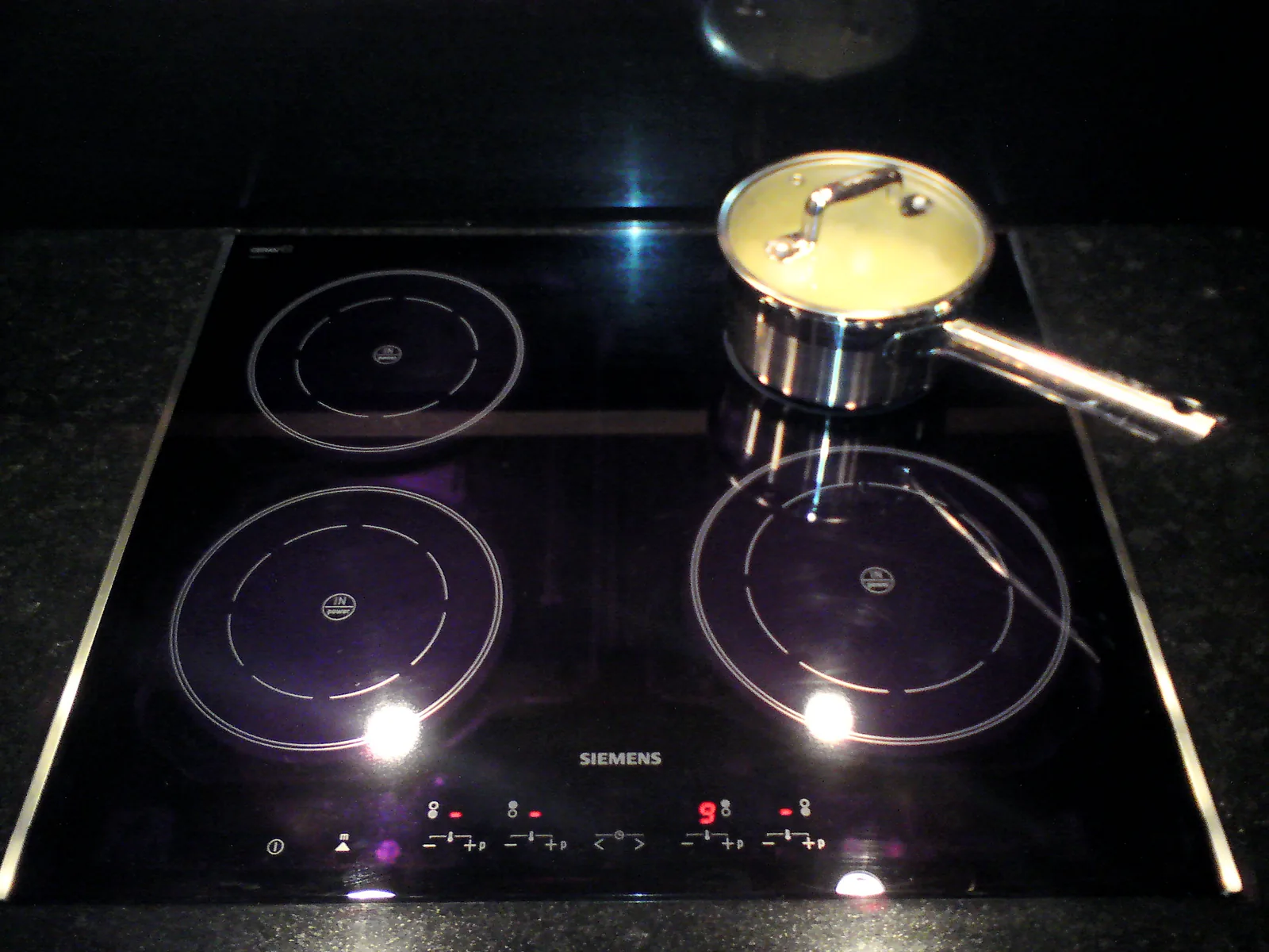
Why the pan must be steel or cast iron
An induction hob heats efficiently only a pan whose base is a ferromagnetic substance, such as steel or cast iron. A ferromagnetic base strengthens the field of the coil and gathers the flux into itself (chapter Magnets, the magnetic dipole and the magnetic field). In addition, steel conducts electricity worse than aluminium, and the eddy currents flow in it only in a thin surface layer with a large resistance, so with the same current in the coil the internal energy of the base grows quickly. Aluminium and copper are not ferromagnetic, and they conduct electricity extremely well. In them the eddy currents spread over a thicker region, the resistance stays small and there is little heating. An ordinary induction hob therefore usually does not heat an aluminium pan: it detects an unsuitable pan and does not start. Many pans have a steel plate under the base for just this reason.
The fibre link: light travels in glass
In a fibre link the transmitter changes the information into pulses of infrared light, which travel in the core of a fibre as thick as a hair by total internal reflection. The refractive index of the core is slightly larger than that of the cladding, and light travelling almost along the axis meets the wall of the core at an angle of incidence larger than the critical angle. In glass with a refractive index of $1.47$ light travels at the speed $v = c : n$, so every kilometre delays the signal by about $4.9\,\mu\text{s}$. Total internal reflection does not waste light, but the glass itself attenuates it: some of the light is absorbed and some is scattered sideways by small variations in the density of the glass. The attenuation of silica glass is smallest at a wavelength of about $1550\,\text{nm}$, so long links use it.
Attenuation limits the length of a link
According to the manufacturer, the attenuation of a common telecommunications fibre is at most $0.18\,\text{dB/km}$ at a wavelength of $1550\,\text{nm}$ and $0.32\,\text{dB/km}$ at a wavelength of $1310\,\text{nm}$ (Corning, product information sheet of the SMF-28 Ultra fibre, 2016). The decibel is familiar from the chapter Loudness of sound (FY5): every $10\,\text{dB}$ means that the power falls to a tenth, and about $3\,\text{dB}$ halves the power. At a wavelength of $1550\,\text{nm}$ the power therefore halves over about $17\,\text{km}$, and after $100\,\text{km}$ less than $2\,\%$ of it is left. The receiver detects pulses even in very weak light, but on long links the light has to be amplified with an optical amplifier about every $50$–$100\,\text{km}$.
Attenuation in decibels
When the power of light is $P_0$ at the start of a fibre and $P$ at the end, the attenuation of the fibre in decibels is
$$\begin{aligned} A &= 10\,\text{dB} \cdot \lg \frac{P_0}{P} \\[6pt] A &= aL \end{aligned}$$
where $A$ is the attenuation ($\text{dB}$), $\lg$ the base-ten logarithm, $a$ the attenuation coefficient of the fibre ($\text{dB/km}$) and $L$ the length of the fibre ($\text{km}$). The formula $A = aL$ holds when the fibre is uniform along its whole length. The attenuations of successive sections in decibels are added, and the ratios of their powers are multiplied: two successive $10\,\text{dB}$ sections attenuate by $20\,\text{dB}$, and the power falls to a tenth of a tenth, that is a hundredth. Splices and sharp bends add to the attenuation, and they are added in the same way. The graph shows that the power falls in the same proportion on every kilometre: the curves are not straight but flatten out.
Voltage of a wireless charger
When the flux through one turn of the receiver coil varies sinusoidally with the peak value $\Phi_0$ and the frequency $f$, an alternating voltage is produced in the coil, and its peak value is found in the same way as in a generator (chapter The generator and alternating current):
$$e_0 = N \cdot 2\pi f \cdot \Phi_0$$
where $e_0$ is the peak value of the voltage ($\text{V}$), $N$ the number of turns of the receiver coil, $f$ the frequency ($\text{Hz}$) and $\Phi_0$ the peak value of the flux through one turn ($\text{Wb}$). A high frequency makes the change of flux fast, so even a small flux is enough. As the distance grows, $\Phi_0$ and with it $e_0$ fall steeply.
Common misconception
Many people think that a wireless charger sends energy far into the room like radio waves, and that a phone could be charged anywhere near the charger. The magnetic field of the charger, however, weakens steeply already over a few centimetres, and energy is transferred only when the receiver coil is in the field right next to the transmitter. Another common mistake is to think that an induction hob heats the glass top, which then warms the pan. The heat is produced in the base of the pan by eddy currents, and the glass warms up only from the hot pan. The third mistake concerns decibels: doubling the attenuation in decibels does not halve the power but raises the ratio of the powers to the second power. $20\,\text{dB}$ leaves $1\,\%$ of the power, not $5\,\%$.
Summary
- A wireless charger is a transformer without an iron core: the flux of the alternating current in the transmitter coil induces a voltage $e_0 = N \cdot 2\pi f \cdot \Phi_0$ in the receiver coil. The flux and the voltage fall steeply when the distance between the coils grows or when they move sideways.
- In wireless charging part of the energy changes into internal energy of the coils: in the measurement, charging took about $47\,\%$ more energy than with a cable.
- In an induction hob the changing field of the coil produces eddy currents in the base of the pan, and they heat the base. A ferromagnetic steel base gets hot well, aluminium and copper poorly, and glass, which does not conduct electricity, not at all.
- In an optical fibre light stays in the core by total internal reflection, but the glass attenuates it: $A = aL$ and $A = 10\,\text{dB} \cdot \lg (P_0 : P)$. Every $10\,\text{dB}$ reduces the power to a tenth.
Optional Return to your predictions
Compare your predictions with the values of the model, the measurement and the theory. Then return to the opening question: what phenomenon is behind each device, and why must the phone be kept right on top of the charger, the pan be made of steel and the light in the fibre be amplified on the way?
Would you change your prediction?
Apply
Worked example
Problem
A fibre link is $80\,\text{km}$ long, and the attenuation coefficient of the fibre is $0.20\,\text{dB/km}$. The transmitter feeds light of power $2.0\,\text{mW}$ into the fibre. How large is the power that reaches the receiver? Ignore the attenuation of the splices.
Step 1/7
Given and find. The length of the fibre is $L = 80\,\text{km}$, the attenuation coefficient is $a = 0.20\,\text{dB/km}$ and the transmitted power is $P_0 = 2.0\,\text{mW}$. We are asked for the power $P$ that reaches the receiver.
Step 2/7
Principle. The fibre is uniform along its whole length, so the attenuation is the attenuation coefficient times the length. The ratio of the powers is solved from the definition of attenuation, and from it the power that arrives.
Step 3/7
Formula solved.
$$\begin{aligned} &A = aL \\[6pt] &\lg \frac{P_0}{P} = \frac{A}{10\,\text{dB}} \\[6pt] &P = P_0 \cdot 10^{-\frac{A}{10\,\text{dB}}} \end{aligned}$$
Step 4/7
Unit conversions. Not needed: the kilometres cancel in the product $aL$, and the power comes out in the same unit as $P_0$. Finally $1\,\text{mW} = 1000\,\mu\text{W}$.
Step 5/7
Substitution. $$\begin{aligned} A &= aL \\ &= 0.20\,\tfrac{\text{dB}}{\text{km}} \cdot 80\,\text{km} \\ &= 16\,\text{dB} \\[6pt] P &= P_0 \cdot 10^{-\frac{A}{10\,\text{dB}}} \\ &= 2.0\,\text{mW} \cdot 10^{-\frac{16\,\text{dB}}{10\,\text{dB}}} \\ &= 2.0\,\text{mW} \cdot 10^{-1.6} \\ &= 0.0502\,\text{mW} \end{aligned}$$
Step 6/7
Result. The power that reaches the receiver is
to two significant figures like the transmitted power $2.0\,\text{mW}$ and the attenuation coefficient.
Step 7/7
Reasonableness. Ten decibels reduce the power to a tenth and twenty to a hundredth, so after $16\,\text{dB}$ the power lies between those, about $2.5\,\%$. Of the power $2.0\,\text{mW}$, $2.5\,\%$ is $0.050\,\text{mW}$, as in the result.
Optional Find the error
Apply to a new situation: how strong a field in the phone
The receiver coil of a phone has $12$ turns, and the area of one turn is $11\,\text{cm}^2$. The frequency of the charger is $140\,\text{kHz}$, and the phone needs a voltage with a peak value of $9.0\,\text{V}$. Assume that at the coil the magnetic field is uniform and perpendicular to the plane of the coil and that the magnetic flux density varies sinusoidally.
How large must the peak value $B_0$ of the magnetic flux density be? Give the answer in millitesla.
Hint 1: a guiding question
Which formula gives the peak value of an alternating voltage when the flux varies sinusoidally? And what is the flux in a uniform field?
Hint 2: what is the connection
$e_0 = N \cdot 2\pi f \cdot \Phi_0$ and $\Phi_0 = B_0 A$, so $B_0 = e_0 : (N A \cdot 2\pi f)$.
Hint 3: an intermediate step
Convert $11\,\text{cm}^2 = 11 \cdot (0.01\,\text{m})^2$ and $140\,\text{kHz} = 140 \cdot 1000\,\text{Hz}$.
Show the solution
Given
number of turns $N = 12$, area of one turn $A = 11\,\text{cm}^2$, frequency $f = 140\,\text{kHz}$, peak voltage $e_0 = 9.0\,\text{V}$
Find
the peak value $B_0$ of the magnetic flux density in millitesla
Principle
The flux through the receiver coil varies sinusoidally, so a sinusoidal voltage is induced in the coil, and its peak value is found as in a generator (chapter The generator and alternating current). The field is assumed to be uniform and perpendicular to the plane of the coil, so the flux through one turn is $\Phi_0 = B_0 A$ (chapter Electromagnetic induction).
Formula
so $B_0 = \dfrac{e_0}{N A \cdot 2\pi f}$
Conversions
Finally $1\,\text{T} = 1000\,\text{mT}$.
Substitution
Answer
$0.78\,\text{mT}$
Two significant figures like the voltage $9.0\,\text{V}$ and the area $11\,\text{cm}^2$.
Reasonableness
Units:
The field is about $15$ times as strong as the Earth's magnetic field, $52\,\mu\text{T}$, but much weaker than that of a fridge magnet. A small field is enough because the high frequency makes the flux change quickly.
Check your understanding
Exit ticket
Answer on your own first and only then open the answer.
- A coin is left between the phone and the wireless charger. Why does the coin get hot?
Answer
The changing magnetic field of the transmitter coil of the charger passes through the coin, and the flux through the coin changes all the time. Eddy currents are induced in the coin, and in the resistance of the coin their electrical energy changes into internal energy of the coin. This is why the charger detects a foreign metal object and stops charging.
- At the end of a fibre the power of the light is a hundredth of the power at the start. What is the attenuation of the fibre in decibels?
Answer
$A$$= 10\,\text{dB} \cdot \lg 100$$= 20\,\text{dB}$Every $10\,\text{dB}$ reduces the power to a tenth, and a tenth of a tenth is a hundredth.
1. Concept: the pan on an induction hob
2. Calculate: the fibre to a house
The fibre link from the exchange to a house is $30\,\text{km}$ long, and the attenuation coefficient of the fibre is $0.20\,\text{dB/km}$.
What percentage of the transmitted power reaches the house? Ignore the attenuation of the splices.
Hint 1: a guiding question
First calculate the attenuation of the whole fibre in decibels.
Hint 2: what is the connection
$A = aL$, and the ratio of the powers is $P : P_0 = 10^{-A/(10\,\text{dB})}$.
Hint 3: an intermediate step
$A = 6.0\,\text{dB}$, so $P : P_0 = 10^{-0.60}$.
Show the solution
Given
length of the fibre $L = 30\,\text{km}$, attenuation coefficient $a = 0.20\,\text{dB/km}$
Find
the share $P : P_0$ of the power that reaches the house, as a percentage
Principle
The fibre is uniform along its whole length, so the attenuation is $A = aL$. The ratio of the powers is solved from the definition of attenuation $A = 10\,\text{dB} \cdot \lg (P_0 : P)$.
Formula
so
Conversions
Not needed: the kilometres cancel in the product $aL$. Finally the ratio is multiplied by one hundred to give a percentage.
Substitution
so
Answer
about $25\,\%$, two significant figures like the attenuation coefficient $0.20\,\text{dB/km}$.
Reasonableness
About $3\,\text{dB}$ halves the power, so $6\,\text{dB}$ halves it twice, and about a quarter, that is $25\,\%$, is left, as in the result.
Practise calculating attenuation in the level 1 and 2 tasks.
Optional 3. Explain: the wireless charger
Explain how a wireless charger transfers energy to a phone although there is no wire between them. Also explain why charging weakens when the phone is lifted off the pad.
Model answer
An alternating current flows in the transmitter coil of the charger and produces a changing magnetic field. Part of the flux of the field passes through the receiver coil of the phone. Because the flux changes all the time, an alternating voltage is induced in the receiver coil according to the law of induction, and the phone uses it to charge its battery. The device is like a transformer without an iron core. The field lines of the transmitter coil loop around its wires and turn back close to the coil. When the phone is lifted, a smaller and smaller part of the flux passes through the receiver, so the voltage falls steeply. Then part of the energy changes only into internal energy of the coils, and charging weakens or stops.
Assess your own answer
Tick the points your own answer already contains.
Review the theory summary and practise with the exercises.
Exercises
Level 1 · basic practice 5 exercises
One formula or one step of reasoning. Core exercises first, the rest is extra practice.
- Exercise 16-1Core
The attenuation coefficient of a telecommunications fibre is $0.18\,\text{dB/km}$. What is the attenuation of a fibre $50\,\text{km}$ long, in decibels?
Answer
$9.0\,\text{dB}$
Show the solution
Given
attenuation coefficient $a = 0.18\,\text{dB/km}$, length of the fibre $L = 50\,\text{km}$
Find
the attenuation $A$ of the fibre in decibels
Principle
The fibre is uniform along its whole length, so every kilometre attenuates by the same number of decibels, and decibels are added. The attenuation of the whole fibre is the attenuation coefficient times the length.
Formula
$A = aL$
Conversions
Not needed: the kilometres cancel in the result, and the attenuation comes out in decibels.
Substitution
$A$$= 0.18\,\tfrac{\text{dB}}{\text{km}} \cdot 50\,\text{km}$$= 9.0\,\text{dB}$Answer
$9.0\,\text{dB}$
Two significant figures like the attenuation coefficient $0.18\,\text{dB/km}$.
Reasonableness
$9\,\text{dB}$ is a little less than $10\,\text{dB}$, so a little more than a tenth of the power is left. This fits the fact that the power halves over about $17\,\text{km}$: $50\,\text{km}$ is about three halvings, and $0.5^3 \approx 0.13$.
- Exercise 16-2Core
The power of light is $2.0\,\text{mW}$ at the start of a fibre and $0.50\,\text{mW}$ at the end. What is the attenuation of the fibre in decibels?
Answer
$6.0\,\text{dB}$
Show the solution
Given
power at the start $P_0 = 2.0\,\text{mW}$, power at the end $P = 0.50\,\text{mW}$
Find
the attenuation $A$ in decibels
Principle
The attenuation in decibels is defined as the base-ten logarithm of the ratio of the powers. The power decreases, so the ratio $P_0 : P$ is greater than one and the attenuation is positive.
Formula
$A$$= 10\,\text{dB} \cdot \lg \dfrac{P_0}{P}$Conversions
Not needed: both powers are in milliwatts, and the unit cancels.
Substitution
$A$$= 10\,\text{dB} \cdot \lg \dfrac{2.0\,\text{mW}}{0.50\,\text{mW}}$$= 10\,\text{dB} \cdot \lg 4.0$$= 6.021\,\text{dB}$Answer
$6.0\,\text{dB}$
Two significant figures like the powers.
Reasonableness
The power falls to a quarter, that is it halves twice. One halving is about $3\,\text{dB}$, so two halvings are about $6\,\text{dB}$, as in the result.
- Exercise 16-3
Assume that the eddy currents in the base of a pan on an induction hob can be described as one current loop with a resistance of $0.010\,\Omega$, in which flows an alternating current with an effective value of $400\,\text{A}$.
At what power do the eddy currents change electrical energy into internal energy of the base? Give the answer in kilowatts.
Answer
$1.6\,\text{kW}$
Show the solution
Given
resistance of the eddy-current loop $R = 0.010\,\Omega$, effective value of the current $I = 400\,\text{A}$
Find
the power $P$ at which electrical energy changes into internal energy of the base, in kilowatts
Principle
The eddy current flows through the resistance of the base, and in a resistance electrical energy changes into internal energy at the power $RI^2$. For an alternating current the formula gives the mean power when $I$ is the effective value of the current (chapter The generator and alternating current).
Formula
$P = RI^2$
Conversions
Finally $1\,\text{kW} = 1000\,\text{W}$.
Substitution
$P$$= 0.010\,\Omega \cdot (400\,\text{A})^2$$= 0.010\,\Omega \cdot 160\,000\,\text{A}^2$$= 1600\,\text{W}$$= 1.6\,\text{kW}$Answer
$1.6\,\text{kW}$
Two significant figures like the resistance $0.010\,\Omega$.
Reasonableness
The power of the cooking zone of an induction hob is usually a few kilowatts, so $1.6\,\text{kW}$ is of the right order of magnitude. Units:
$\Omega \cdot \text{A}^2$$= \text{V} \cdot \text{A}$$= \text{W}$ - Exercise 16-4
The magnetic field of a wireless charger is uniform at the receiver coil of a phone and perpendicular to the plane of the coil, and the peak value of the magnetic flux density is $0.50\,\text{mT}$. The area of one turn of the coil is $12\,\text{cm}^2$.
What is the peak value of the flux through one turn? Give the answer in microwebers.
Answer
$0.60\,\mu\text{Wb}$
Show the solution
Given
peak value of the magnetic flux density $B_0 = 0.50\,\text{mT}$, area of one turn $A = 12\,\text{cm}^2$, field uniform and perpendicular to the plane of the coil
Find
the peak value $\Phi_0$ of the flux through one turn in microwebers
Principle
In a uniform field perpendicular to the surface the flux is the magnetic flux density times the area (chapter Electromagnetic induction). When the flux density is greatest, the flux is also greatest.
Formula
$\Phi = BA$, so $\Phi_0 = B_0 A$
Conversions
$B_0$$= 0.50\,\text{mT}$$= 0.50 \cdot 10^{-3}\,\text{T}$$A$$= 12\,\text{cm}^2$$= 12 \cdot (0.01\,\text{m})^2$$= 1.2 \cdot 10^{-3}\,\text{m}^2$Finally $1\,\text{Wb} = 10^{6}\,\mu\text{Wb}$.
Substitution
$\Phi_0$$= 0.50 \cdot 10^{-3}\,\text{T} \cdot 1.2 \cdot 10^{-3}\,\text{m}^2$$= 6.0 \cdot 10^{-7}\,\text{Wb}$$= 0.60\,\mu\text{Wb}$Answer
$0.60\,\mu\text{Wb}$
Two significant figures like the initial data.
Reasonableness
Units: $\text{T} \cdot \text{m}^2 = \text{Wb}$. The flux is small because both the field and the area are small; because of the high frequency even such a small flux induces volts in the coil.
- Exercise 16-5
Assume that a wireless charger takes a power of $10.0\,\text{W}$ from the wall socket and a power of $7.2\,\text{W}$ is transferred to the battery of the phone.
What is the efficiency of the charging? Give the answer as a percentage.
Answer
$72\,\%$
Show the solution
Given
power taken by the charger $P_\text{in} = 10.0\,\text{W}$, power transferred to the battery $P_\text{battery} = 7.2\,\text{W}$
Find
the efficiency $\eta$ of the charging as a percentage
Principle
Efficiency is the share of the useful power in the power taken. Here the useful power is the power transferred to the battery; the rest changes into internal energy of the coils and electronics of the charger and the phone.
Formula
$\eta$$= \dfrac{P_\text{battery}}{P_\text{in}}$Conversions
Not needed: both powers are in watts. Finally the ratio is multiplied by one hundred to give a percentage.
Substitution
$\eta$$= \dfrac{7.2\,\text{W}}{10.0\,\text{W}}$$= 0.72$$= 72\,\%$Answer
$72\,\%$
Two significant figures like the power transferred to the battery, $7.2\,\text{W}$.
Reasonableness
The efficiency is below $100\,\%$, as it must be. The power wasted is $10.0\,\text{W} - 7.2\,\text{W} = 2.8\,\text{W}$, which shows in the fact that the charger and the phone get warm during charging.
Level 2 · applied practice 4 exercises
Two steps, working with measured data, a unit conversion or rearranging a formula. Core exercises first, the rest is extra practice.
- Exercise 16-6Core
The receiver coil of a phone has $10$ turns. The frequency of the charger is $140\,\text{kHz}$, and the magnetic flux through one turn varies sinusoidally with a peak value of $0.40\,\mu\text{Wb}$.
What is the peak value of the voltage induced in the coil?
Answer
$3.5\,\text{V}$
Show the solution
Given
number of turns $N = 10$, frequency $f = 140\,\text{kHz}$, peak value of the flux through one turn $\Phi_0 = 0.40\,\mu\text{Wb}$
Find
the peak value $e_0$ of the induced voltage
Principle
The flux varies sinusoidally, so a sinusoidal voltage is induced in every turn, and its peak value is the peak value of the rate of change of the flux, $2\pi f \cdot \Phi_0$, as in a generator. The voltages of the turns add up.
Formula
$e_0 = N \cdot 2\pi f \cdot \Phi_0$
Conversions
$f$$= 140\,\text{kHz}$$= 140 \cdot 1000\,\text{Hz}$$= 1.40 \cdot 10^{5}\,\text{Hz}$$\Phi_0$$= 0.40\,\mu\text{Wb}$$= 0.40 \cdot 10^{-6}\,\text{Wb}$Substitution
$e_0$$= 10 \cdot 2\pi \cdot 1.40 \cdot 10^{5}\,\text{Hz} \cdot 0.40 \cdot 10^{-6}\,\text{Wb}$$= 3.519\,\text{V}$Answer
$3.5\,\text{V}$
Two significant figures like the flux $0.40\,\mu\text{Wb}$.
Reasonableness
Units:
$\text{Hz} \cdot \text{Wb}$$= \tfrac{1}{\text{s}} \cdot \text{V}\cdot\text{s}$$= \text{V}$A voltage of a few volts is enough for the electronics of a phone, which rectifies it to charge the battery.
- Exercise 16-7Core
The transmitter of a fibre link feeds a power of $1.0\,\text{mW}$ into the fibre, and the receiver detects the pulses when the power is at least $1.0\,\mu\text{W}$. The attenuation coefficient of the fibre is $0.20\,\text{dB/km}$.
What is the greatest possible length of the link without an amplifier? Ignore the attenuation of the splices.
Answer
$150\,\text{km}$
Show the solution
Given
transmitted power $P_0 = 1.0\,\text{mW}$, smallest power that can be received $P = 1.0\,\mu\text{W}$, attenuation coefficient $a = 0.20\,\text{dB/km}$
Find
the greatest length $L$ of the link in kilometres
Principle
The receiver detects the pulses when the power is at least $1.0\,\mu\text{W}$, so the greatest permitted attenuation follows from the ratio of the powers. The fibre is uniform along its whole length, so the attenuation is $A = aL$, and the length is solved from it.
Formula
$A$$= 10\,\text{dB} \cdot \lg \dfrac{P_0}{P}$$A = aL$, so $L = \dfrac{A}{a}$
Conversions
$P_0$$= 1.0\,\text{mW}$$= 1.0 \cdot 10^{-3}\,\text{W}$$P$$= 1.0\,\mu\text{W}$$= 1.0 \cdot 10^{-6}\,\text{W}$Substitution
$A$$= 10\,\text{dB} \cdot \lg \dfrac{1.0 \cdot 10^{-3}\,\text{W}}{1.0 \cdot 10^{-6}\,\text{W}}$$= 10\,\text{dB} \cdot \lg 1000$$= 30\,\text{dB}$so
$L$$= \dfrac{30\,\text{dB}}{0.20\,\text{dB/km}}$$= 150\,\text{km}$Answer
$150\,\text{km}$
That is $1.5 \cdot 10^{2}\,\text{km}$, two significant figures like the attenuation coefficient $0.20\,\text{dB/km}$.
Reasonableness
The power may fall to a thousandth, that is three times to a tenth, which is $3 \cdot 10\,\text{dB}$. When every $10\,\text{dB}$ needs $50\,\text{km}$ of fibre, the length is $150\,\text{km}$. This is of the same order of magnitude as the amplifier spacing of real links.
- Exercise 16-8
The cooking zone of an induction hob takes a power of $2.0\,\text{kW}$ from the mains. Assume that $85\,\%$ of the power is transferred to the water in the pan. The pan contains $1.5\,\text{kg}$ of water at a temperature of $15\,{}^\circ\text{C}$.
How long does it take to heat the water to the boiling point, $100\,{}^\circ\text{C}$? The specific heat capacity of water is $4190\,\tfrac{\text{J}}{\text{kg}\cdot\text{K}}$. Give the answer in minutes.
Answer
$5.2\,\text{min}$
Show the solution
Given
power of the cooking zone $P = 2.0\,\text{kW}$, share transferred to the water $\eta = 85\,\%$, mass of water $m = 1.5\,\text{kg}$, initial temperature $15\,{}^\circ\text{C}$, final temperature $100\,{}^\circ\text{C}$, specific heat capacity of water from the table $c = 4190\,\tfrac{\text{J}}{\text{kg}\cdot\text{K}}$
Find
the heating time $t$ in minutes
Principle
The water stays liquid throughout the heating, so the energy it needs is $Q = cm\Delta T$. The eddy currents heat the base, and by assumption $85\,\%$ of the power taken by the hob is transferred to the water, so the power transferred to the water is $\eta P$. The time is the energy divided by the power.
Formula
$Q = cm\Delta T$ and $Q = \eta P t$, so $t = \dfrac{cm\Delta T}{\eta P}$
Conversions
$\Delta T$$= 100\,{}^\circ\text{C} - 15\,{}^\circ\text{C}$$= 85\,{}^\circ\text{C}$$= 85\,\text{K}$(a temperature difference is the same in degrees Celsius and in kelvins), $P = 2.0\,\text{kW} = 2000\,\text{W}$ and $\eta = 85\,\% = 0.85$. Finally $1\,\text{min} = 60\,\text{s}$.
Substitution
$t$$= \dfrac{4190\,\tfrac{\text{J}}{\text{kg}\cdot\text{K}} \cdot 1.5\,\text{kg} \cdot 85\,\text{K}}{0.85 \cdot 2000\,\text{W}}$$= \dfrac{534\,225\,\text{J}}{1700\,\text{W}}$$= 314.3\,\text{s}$$= 5.238\,\text{min}$Answer
$5.2\,\text{min}$
Two significant figures like the power $2.0\,\text{kW}$ and the mass $1.5\,\text{kg}$.
Reasonableness
From experience, about a litre and a half of water boils on an induction hob in a few minutes. An estimate with round numbers:
$4000 \cdot 1.5 \cdot 85$$\approx 500\,000\,\text{J}$$500\,000\,\text{J} : 1700\,\text{W}$$\approx 300\,\text{s}$$= 5\,\text{min}$ - Exercise 16-9
In a measurement (Ravenscraft, OneZero, 2020) charging a phone from empty to full took $14.26\,\text{Wh}$ of energy from the wall socket with a cable charger and $21.01\,\text{Wh}$ with a charging pad. Assume that the phone is charged from empty to full once a day for a year ($365$ days).
How much more energy does the charging pad use in a year than the cable charger? Give the answer in kilowatt-hours.
Answer
$2.46\,\text{kWh}$
Show the solution
Given
from the measurement, the energy of the cable charger $E_1 = 14.26\,\text{Wh}$ and of the charging pad $E_2 = 21.01\,\text{Wh}$ per charge, $365$ charges a year
Find
the extra energy consumption $\Delta E$ of the charging pad in a year in kilowatt-hours
Principle
In every charge the pad takes $E_2 - E_1$ more energy from the wall socket than the cable charger. By assumption the phone is charged every day in the same way from empty to full, so the increase over a year is the increase of one charge times the number of charges.
Formula
$\Delta E = 365 \cdot (E_2 - E_1)$
Conversions
Finally $1\,\text{kWh} = 1000\,\text{Wh}$.
Substitution
$\Delta E$$= 365 \cdot (21.01\,\text{Wh} - 14.26\,\text{Wh})$$= 365 \cdot 6.75\,\text{Wh}$$= 2463.75\,\text{Wh}$$= 2.464\,\text{kWh}$Answer
$2.46\,\text{kWh}$
Three significant figures like the difference $6.75\,\text{Wh}$.
Reasonableness
Estimate: about $7\,\text{Wh}$ a day is about $2.5\,\text{kWh}$ a year. For one person this is a small amount, about the same as a $1\,\text{kW}$ kettle uses in two and a half hours, but the combined waste of millions of phones is large.
Level 3 · challenging 3 exercises
Optional: application, two ideas together or a new situation where you reason for yourself.
- Exercise 16-10
The submarine cable C-Lion1 is $1172\,\text{km}$ long (Cinia, 2016).
Assume that the attenuation coefficient of its fibres is $0.18\,\text{dB/km}$ and that the attenuation of one section of fibre may be at most $20\,\text{dB}$ before an optical amplifier restores the power of the light. The sections are of equal length, and the amplifiers are between the sections; the transmitter and the receiver are at the ends of the cable.
What is the smallest number of amplifiers the cable must have?
Answer
$10$
Show the solution
Given
length of the cable $L = 1172\,\text{km}$, attenuation coefficient $a = 0.18\,\text{dB/km}$, greatest attenuation of one section $A_\text{max} = 20\,\text{dB}$
Find
the smallest number of amplifiers
Principle
The fibre is uniform along its whole length, so the attenuation of a section is $A = a\,l$, where $l$ is the length of the section. A section may be at most so long that the attenuation is $20\,\text{dB}$. Enough sections are needed to cover the whole cable, and because the transmitter and the receiver are at the ends, there is one amplifier fewer than there are sections.
Formula
$A_\text{max} = a\,l_\text{max}$, so
$l_\text{max}$$= \dfrac{A_\text{max}}{a}$the number of sections $k \ge \dfrac{L}{l_\text{max}}$ and the number of amplifiers $k - 1$
Conversions
Not needed: the lengths are in kilometres and the attenuations in decibels.
Substitution
$l_\text{max}$$= \dfrac{20\,\text{dB}}{0.18\,\text{dB/km}}$$= 111.1\,\text{km}$so
$\dfrac{L}{l_\text{max}}$$= \dfrac{1172\,\text{km}}{111.1\,\text{km}}$$= 10.55$Thus $k = 11$ sections are needed, and $11 - 1 = 10$ amplifiers.
Answer
at least $10$ amplifiers. The number is a whole number, and the number of sections is rounded up, because $10$ sections would be too long.
Reasonableness
Without amplifiers the attenuation of the whole cable would be $0.18\,\text{dB/km} \cdot 1172\,\text{km} = 211\,\text{dB}$, and $211\,\text{dB} : 20\,\text{dB} \approx 10.5$ sections. The length of a section, $1172\,\text{km} : 11 = 107\,\text{km}$, is slightly above the typical amplifier spacing of $50$–$100\,\text{km}$ in real links.
- Exercise 16-11
The coil of an induction hob at a frequency of $25\,\text{kHz}$ produces in the base of a pan a sinusoidally varying magnetic field whose magnetic flux density has a peak value of $4.0\,\text{mT}$.
Assume that the field is uniform and perpendicular to the base, that the eddy currents in the base can be described as one loop with a radius of $8.0\,\text{cm}$ and a resistance of $0.050\,\Omega$, and that the magnetic field of the eddy current itself is ignored.
At what mean power does the base heat up? Give the answer in kilowatts.
Answer
$1.6\,\text{kW}$
Show the solution
Given
frequency $f = 25\,\text{kHz}$, peak value of the magnetic flux density $B_0 = 4.0\,\text{mT}$, radius of the loop $r = 8.0\,\text{cm}$, resistance of the loop $R = 0.050\,\Omega$, field uniform and perpendicular to the base
Find
the mean power $P$ at which the base heats up, in kilowatts
Principle
The flux $\Phi = BA$ through the loop varies sinusoidally, so a sinusoidal voltage is induced in the loop, with the peak value $e_0 = 2\pi f \cdot \Phi_0$, as in a one-turn generator (chapter The generator and alternating current). The electrical energy of the eddy current changes into internal energy in the resistance; the mean power is calculated from the effective voltage $U = e_0 : \sqrt{2}$.
Formula
$\Phi_0 = B_0 \cdot \pi r^2$, $e_0 = 2\pi f \cdot \Phi_0$, $U = \dfrac{e_0}{\sqrt{2}}$ and $P = \dfrac{U^2}{R}$, so
$P$$= \dfrac{(2\pi f \cdot B_0 \cdot \pi r^2)^2}{2R}$Conversions
$f$$= 25\,\text{kHz}$$= 25 \cdot 1000\,\text{Hz}$$= 2.5 \cdot 10^{4}\,\text{Hz}$$B_0$$= 4.0\,\text{mT}$$= 4.0 \cdot 10^{-3}\,\text{T}$$r$$= 8.0\,\text{cm}$$= 8.0 \cdot 0.01\,\text{m}$$= 0.080\,\text{m}$Finally $1\,\text{kW} = 1000\,\text{W}$.
Substitution
$e_0$$= 2\pi \cdot 2.5 \cdot 10^{4}\,\text{Hz} \cdot 4.0 \cdot 10^{-3}\,\text{T} \cdot \pi \cdot (0.080\,\text{m})^2$$= 12.63\,\text{V}$so
$P$$= \dfrac{(12.63\,\text{V})^2}{2 \cdot 0.050\,\Omega}$$= 1596\,\text{W}$$= 1.596\,\text{kW}$Answer
$1.6\,\text{kW}$
Two significant figures like the flux density $4.0\,\text{mT}$, the radius $8.0\,\text{cm}$ and the resistance $0.050\,\Omega$.
Reasonableness
The effective voltage is $12.63\,\text{V} : \sqrt{2} = 8.93\,\text{V}$ and the effective current $8.93\,\text{V} : 0.050\,\Omega = 179\,\text{A}$; the power $8.93\,\text{V} \cdot 179\,\text{A} \approx 1600\,\text{W}$ agrees. The result is of the order of magnitude of the power of a cooking zone; in reality the field of the eddy current itself reduces the current, so the result is an upper limit.
- Exercise 16-12
The transmitter of a fibre link feeds a power of $1.0\,\text{mW}$ into the fibre, and the receiver needs a power of at least $10\,\mu\text{W}$. The attenuation coefficient of the fibre is $0.20\,\text{dB/km}$, and the link has four splices, each of which attenuates by $0.50\,\text{dB}$.
The refractive index of the glass of the fibre is $1.47$.
How long does it take a light pulse to travel from end to end of the longest possible link, when the pulse travels along the axis of the fibre? The speed of light in a vacuum is $3.00 \cdot 10^8\,\text{m/s}$. Give the answer in milliseconds.
Answer
$0.44\,\text{ms}$
Show the solution
Given
transmitted power $P_0 = 1.0\,\text{mW}$, smallest power needed $P = 10\,\mu\text{W}$, attenuation coefficient $a = 0.20\,\text{dB/km}$, four splices each attenuating by $0.50\,\text{dB}$, refractive index of the glass $n = 1.47$, speed of light in a vacuum $c = 3.00 \cdot 10^8\,\text{m/s}$
Find
the travel time $t$ of a light pulse from end to end of the longest link, in milliseconds
Principle
The total attenuation of the link may be at most the amount given by the ratio of the powers. Decibels are added, so the part that is not used up by the splices is left for the fibre, and from it the greatest length is found. In glass light travels at the speed $v = c : n$ (chapter Total internal reflection and optical fibre), and a pulse travelling along the axis covers the length of the fibre.
Formula
$A$$= 10\,\text{dB} \cdot \lg \dfrac{P_0}{P}$$A = aL + 4 \cdot 0.50\,\text{dB}$, so
$L$$= \dfrac{A - 4 \cdot 0.50\,\text{dB}}{a}$and $t = \dfrac{L}{v} = \dfrac{nL}{c}$
Conversions
$P_0$$= 1.0\,\text{mW}$$= 1.0 \cdot 10^{-3}\,\text{W}$$P$$= 10\,\mu\text{W}$$= 1.0 \cdot 10^{-5}\,\text{W}$length $90\,\text{km} = 90 \cdot 1000\,\text{m}$; finally $1\,\text{s} = 1000\,\text{ms}$.
Substitution
$A$$= 10\,\text{dB} \cdot \lg \dfrac{1.0 \cdot 10^{-3}\,\text{W}}{1.0 \cdot 10^{-5}\,\text{W}}$$= 10\,\text{dB} \cdot \lg 100$$= 20\,\text{dB}$$L$$= \dfrac{20\,\text{dB} - 2.0\,\text{dB}}{0.20\,\text{dB/km}}$$= 90\,\text{km}$$= 90\,000\,\text{m}$so
$t$$= \dfrac{1.47 \cdot 90\,000\,\text{m}}{3.00 \cdot 10^8\,\text{m/s}}$$= 4.41 \cdot 10^{-4}\,\text{s}$$= 0.441\,\text{ms}$Answer
$0.44\,\text{ms}$
Two significant figures like the powers and the attenuation coefficient.
Reasonableness
Without splices the fibre could be $100\,\text{km}$, so the splices shorten the link a little, as they should. In glass light travels about $200\,\text{km}$ in a millisecond, so $90\,\text{km}$ takes a little less than half a millisecond.
Photographs
- Induktionshäll. Grillo. source, CC BY-SA 3.0
